![]()
![]()
Home Index
On
|
||
| Back | Home Index |
On |
THE DIESEL SYSTEMApart from changing the engine's oil, oil filter, changing/cleaning the air filter, and making sure it is not allowed to overheat there is little more anyone can do to prolong engine life. The most vulnerable part of the diesel engine is the fuel system.
The fuel system takes fuel at zero pressure (gauge pressure for the boffins) and increases it to between 20,000 and 30,000 psi - about 1000 times the pressure in your car tyres. This pressure then forces fuel through tiny holes into the engine forming a mist of fuel droplets. Most of the high pressure system uses no form of sealing, relying on a virtually perfect fit between parts to prevent excess leakage.
The parts are made in batches and then each part is tried with every other part until a pair that makes a perfect fit are found. These mated parts are then kept together for life.
As the parts wear the measuring and delivery of fuel gets less precise until the engine's starting, fuel economy, power, and exhaust smoke are compromised.
You will see that wear is the problem, and the two things that accelerate wear are dirt and water. The whole design and maintenance of the fuel system must be to prevent dirt and water reaching the injector pump and injectors on the engine.
BUGS - diesel viruses?
Another problem is that diesel fuel is capable of supporting microbes, especially when any water is present. The bodies of these eventually clog filters and, I am told, turn the fuel to jelly. Again, your maintenance should be directed towards minimising this problem.
In very cold temperatures the fuel also starts to form little plates of wax that block the filters, eventually the fuel will turn to jelly. All returns to normal as the temperature rises.
This is not normally a problem for craft in British waters.
AIR
If air builds up in the injector pump or other parts of the high-pressure circuit, the air will just be compressed, rather than squirting the fuel about. The engine then stops.
The design of the system and your maintenance should be directed to preventing air becoming trapped in the system.
Self bleeding systems - Some systems are said to be self bleeding, that is if air gets into them (like when you run out of fuel) the system will get rid of the air without your help. THESE SYSTEMS OFTEN PUT GREAT DEMANDS UPON THE STARTING BATTERY, so you are advised to treat these systems as non-self bleeding, simply to prolong the life of the starting system.
Whatever type of injector pump(s) your engine uses the fuel system should conform to the block diagram shown below.
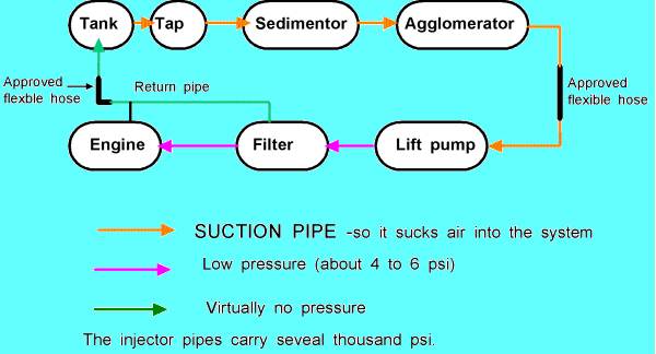
Some installations do not run the return (leak off pipe) back to the tank. In your lecturer's view this is bad practice because any small amounts of air in the fuel will build up and eventually stop the engine, rather than being safely returned to the tank where they can separate from the fuel.
The fuel injection system can be placed into one of five categories, depending on the design of injector pump. These are listed and illustrated below. Please note these are vehicle diagrams and do not show sedimentors and agglomerators which are placed between the tank and lift pump.
INLINE PUMP.
SEPARATE PUMPS (Lister)
The diagram for this will be nearly the same as the one above, except the single injector pump will be replaced by a number of individual pumps.
DPA PUMP (Two types)
ROTARY PUMP
This diagram is for the "self bleeding" version. A marine design would, ideally, have a link to the leak off pipe from the injector pump.
COMMON RAIL
This is an ecu controlled electronic system that is probably best left to vehicles for another 5 to 10 years. This system is not covered.
"HOMEWORK" TASK
Inspect your boat and identify which fuel system most closely resembles yours.Identify the suction pipes, the low pressure pipes, the injector pipes, and the leak off pipe.
Pipe work
Look at the diagram above. Which is most relevant to your boat?
Identify the problem created by less than perfect pipe work in each part of the system.
SUCTION SECTION - A slight leak here will not even show, but air will be sucked into the system leading to an air lock and the need to bleed.
If you have to keep bleeding the system, suspect a poor joint in this part.
LOW PRESSURE - between lift pump and injector pump. A leak here will initially show as "dampness" around the leak, especially when the engine is running. It might not leak at all with the engine stationary. Such a leak can only get worse. Eventually the fuel will all leak from the joint so none is left for the engine, so it just stops.
HIGH PRESSURE (Injector pipes) - These will just spray out. The engine will misfire, the fuel will get hot and smell.
Keep your skin well away from such a leak until the engine is stopped - the spray can go straight through the skin, leading to possible amputation!
LEAK OFF - Minor "leaks" will not show because there is no pressure in this pipe if the system is in good condition. A full fracture will leak, and the more worn the system, the worse the leak.
This pipe is used to carry the small amount of air that is dissolved in the fuel back to the top of the tank. With a bit of luck, minor amounts of air from faults in the suction pipes will also be removed this way. Despite some marine and vehicle practice your lecturer would always fit a full leak off system.
Any connection to the filter or injector pump should be restricted, usually by using a union bolt with a very small hole in it.
THE PARTS
We will now review the parts in the system and look at the maintenance required by each part.
THE TANK
This tank is the ideal, few will be in a position to specify their fuel tank, and even those who try might well not get what they think they asked for.
The diagram is pretty much self explanatory. The baffles are to stop the fuel surging about and mixing the water and dirt into the fuel being used. The slope (the whole tank can be sloped) is to ensure the water and dirt falls to the lowest part where you can drain it off.
The cap is needed on the drain tap to comply with the boat safety scheme. (The drain tap is needed to prevent you filling your bilge with diesel when you drop a simple drain plug!).
The inside of a diesel tank is normally untreated steel (the fuel stops rust). Galvanised tanks should not be used with diesel fuel because there is a possibility that diesel will react with the zinc and cause problems.
Tank maintenance
Those bugs!!! The bugs need moisture to survive so it is vital to keep water out of the tank. This is done in two ways:
Keeping the tank full so there is no, or very little, room for condensation - especially important during the winter.
Drain the tank regularly to ensure any water that has gathered is removed. Experience will tell you how often. It must be done at the end of the season
If you have no drain tap use a "drill pump" and a length of copper tube to fish around the bottom of the tank to extract any water. Balasting the boat to give a marked list a week or so before will help to ensure you know where the water will be.
Let the fuel you have removed stand in a glass jar so any water falls to the bottom so you can see it.
I use a proprietory "water remover" in my fuel after a discussion with Wynn's Technical Director.
If possible the strainer on the end of the pick up pipe should be checked for cleanliness - again once a year.
There is little else that can be done unless you have an inspection plate that would allow manual internal inspection.
All fuel pipes should be of steel or copper, they should be clipped at no more than 300mm (1 foot) intervals, and any joints should be compression fittings.
Copper pipes work harden - that is as they move or vibrate they gradually become harder and harder until they crack. Thus the need for lots of clips to prevent vibration. A copper pipe which is suspect can be softened by removal from the boat, heating along its full length to red hot, and cooling it.
This is especially important for internal pipes in Listers;
if one of these leaks the engine can draw fuel fumes from the sump and "run away" - that is rev up and refuse to stop on the stop control - any engine can do this with a calor gas leak!
Flexible hoses
All engines vibrate, however they are mounted, so fuel pipes running to engines will also vibrate.
Tradition (and some BSS examiners) advocate putting two or three (say) 4" coils in a solid copper pipe to form a sort of flexible connection between the hull and engine. Your lecturer would advise very strong opposition to this view because of the problem of work hardening.
The coils will have a natural vibration frequency at which they will gradually increase the degree to which they "wave about" until they fracture. The problems of work hardening makes this worse.
Eventually you will come across the circumstances where the vibration from the engine matches those of the coil - you are virtually guaranteed a pipe failure - without any warning.
"Rubber" flexible hoses naturally damp vibration and also start to show signs of failure long before they actually do fail, thus the correct flexible hoses running between the engine and hull pipe work are the safest option - even if they are not traditional. A typical flexible hose is illustrated below.
Make sure the hose assembly complies with the BSS and also fit it in such a way that the examiner can see the BS or ISO number marking.
Please note that hoses clipped with worm drive or self-assembly clips will not do.
Pipe work maintenance
Check all clips are tight and the pipes are not vibrating.
Put a pair of spanners on each compression fitting and "tweek" them to make sure the joint is not working loose. Do not seek to actually tighten them, if you do you will eventually crush the olive and pipe so it leaks - fuel out or air in.
Check the flexible hoses to make sure there are no signs of abrasion, perishing, or strain.
Check all other unions for signs of leak and to ensure tightness.
Injector leak off pipes
Whilst I am aware of "problems" related to the enforced use of solid leak off pipes I would make a couple of points:
All the early BMC 2.2, 1.5, & Perkins engines had solid leak off pipes fitted by the factory for vehicle use.
The use of rubber "bushes" clipped between leak off pipe and engine will damp vibrations that lead to failure.
A number of "marinised" engines do not have their fuel filters adequately supported, thus they vibrate and cause the leak off pipe to fail.
The filter bracket should have a minimum thickness of about 6mm (1/4")
Clumsy or unskilled fitting of leak off pipes strains the joints and again leads to failure.
The pipe itself should be gently bent and adjusted until the union bolts drop into place WITHOUT springing the pipe into place. If necessary the pipe should then be annealed.
This is the first "filter" like object found after leaving the tank. It is illustrated below.
Apart from washers (which should be copper), no plastic parts are allowed.
Rubber sealing rings are allowed and they will be found between each part.
The bowl at the base must not be plastic or glass (OK so there is one approved plastic version, but try persuading the BSS examiner when the marks have worn off!.)
Operation
Fuel is pumped in, the inverted cone and the angle of the inlet cause it to swirl round, gaining speed as it moves down the cone.
Any large pieces of dirt or water are "centrifuged" to the edge where they drop into the bowl to await removal.
There is a school of thought that inland boats rarely require enough fuel to make the speed of the swirling sufficient to remove the dirt etc. This ignores the fact that when you need power, like in flood conditions, the last thing you want is water stopping the fuel system working!
Sedimentor maintenance
Strip and clean during layup or refit.
If you do find a lot of water then clean the tank and decrease the time interval between cleaning.
Inspect and replace the rubber seals as required.
AGGLOMERATOR
This should be mounted close to the sedimentor.
The comments about glass & plastic still apply.
OPERATION
This is a "pocket" filter made up of a roll of folded and glued paper so it forms a series of pockets, open at the top.
Fuel is forced into the pocket, but the very small droplets of water (left by the sedimentor) are too large to easily pass through the pores in the pockets. They gradually increase in size as they merge so a larger surface area is exposed to the incoming fuel pressure. At a certain point the internal pressure will be sufficient to force the whole drop through the pore. Now, being larger, they are carried downwards by the fuel to exit through tangential slots at the bottom of the element.
The slots cause the fuel and water to spin, the fuel being lighter quickly alters its path to flow up through the centre of the element, the water dropping into the bowel.
** WARNING ** Some manufacturers supply ordinary pleated elements where the water exits horizontally, at any vertical point, into the centre of the filter. This part contains upward moving fuel, thus increasing the likelihood of water droplets bypassing the collecting bowl.
At this time I have only identified Lucas & Mann & Hummel elements as being of the type I would use.
The element will also remove some dirt particles.
Agglomerator service
Change the element, seals, and clean during layup or refit.
Again if there is evidence of heavy contamination, clean tank and decrease service intervals.
FUEL LIFT PUMP
Most boats will have a mechanical lift pump mounted on the engine, a few modern engines use a separate electric pump which MIGHT allow self bleeding.
The electric pump will be of the centrifugal type (see engine water pump, later) and will be sealed for life. Providing its wiring is kept in good condition and you ensure it has an electrical supply it is unlikely to give trouble. If it fails to work with an electrical supply then change it.
A Mechanical Pump is illustrated below.
The marine version of this pump is likely to have its inlet and outlet in the side of the body. It will have a cap fitted with a single bolt or screw. Under this cap is a gauze strainer and sediment trap. It should also have an external lever fitted to move the diaphragm when bleeding the system.
Provided the pump is mounted vertically, (so the cap is horizontal) this might be the easiest place to check for water.
- Turn off fuel tap.
- Loosen screw and remove cap.
- Inspect for water/dirt - if present then clean.
- Inspect rubber seal in cap for condition.
- Loosely replace cap and turn on fuel tap - if you are lucky the fuel will fill the pump by gravity.
As fuel spills from pump tighten cap.
If you are unlucky and fuel does not spill out then bleed the system - see later.
FUEL FILTER
This uses many common components together with the sedimentor and agglomerator.
The fuel passes sideways through the filter that is designed to remove the smallest dirt particles. The sedimentor and agglomerator are needed to prevent this fine filter becoming clogged.
SERVICE
Change the element and seals as stated by the engine manufacturer. If you have no information then change them whenever you change the engine oil and filter. In any case change them once a year.
INJECTOR PUMP
This contains some very high precision parts and also needs timing to the engine. It is not something anyone without experience should attempt to remove - let alone mend.
It will need sending to a specialist - every main town has at least one diesel injection specialist.
INJECTORS
Whatever their shape all injectors work on the same principle, the only things that alter are the nozzle type and how the injection pressure is adjusted.
Again they must be overhauled by a specialist, but for the sake of completeness an injector is illustrated. This one is off a modern Ford engine. Others will have a different method of mounting and the inlet and leak off connections in a different place.
The main purpose of this illustration is so you know what the nozzle is.
Nozzles come in about four types:
Single hole
Multi hole
Pintle (like this one)
Pintaux
All injector nozzles need treating as fragile, but the last two need extra special care because they have a minuscule cone hanging out of the nozzle (the pintle).
If the pintle is knocked off upon removal you will have to pay for a new nozzle.
Injector Servicing
There is NO SERVICING that can be undertaken on an injector that does not require special equipment and knowledge.The spray leaving the injector WILL PENETRATE THE SKIN so do not even think about trying to see how an injector is working.
Providing you clean the area around the injector first, you can unbolt it and take it to a specialist (taking extra special care of the nozzle).
The indications that the injectors require cleaning are:
Smokey exhaust - often blackish and after a period on tickover
Poor cold starting (make sure the heater plugs are working first).
Noise - especially on tickover.
Loss of power.
None of this helps if you have just bought a boat, and as the changes are so slow, it is little help to others without considerable experience.
Refitting injectors
All injector mountings should be done up to a torque (a measurement of tightness), although experience would indicate that providing you do the "two bolt" type mounts up evenly and do not have a show of strength, all will be well. Remember to remove the plastic cap the specialist will put on the nozzle and save it to protect the injector next time.
Heat shields
Between the nozzle and the cylinder head, there almost certainly will be a copper washer and there could also be a heat shield. These MUST be renewed whenever the injector is refitted, as should any copper washers on the leak off pipe.
INJECTOR PIPES
INJECTOR PIPES MUST NEVER BE BENT to make them clear the injector - loosen them from the pump end so they swing clear.
Bending pipes will lead to premature failure.
The little plates with rubber bushes clamped to the injector pipes are used to damp vibration, so they must always be refitted, otherwise the pipe is likely to fail through vibration. (Perkins did tell me they were called "twit plates" on their V12 engine - to prevent twits putting the pipes on wrong, but you know the real purpose).
Whenever you open the system between the tank and injector pump, or if you run out of fuel you will have to bleed the system.
"Homework" task
Find the lift pump on your boat and then follow the pipe to the injector pump - the thing with injector pipes fitted to it. You should pass the filter.
Now look for the smallest bolt/screw on the top of the filter and at least one small bolt or screw on the body of your injector pump.
Check these are the bleed screws in your manual.
Hopefully you will now know the bleed screws.
The bleeding
- Loosen - not remove - the bleed screws, say three turns or so.
- Place rag or a pot under the filter and injector pump to catch any diesel fuel.
- Pump the priming lever on the lift pump or priming pump whilst you watch the bleed screw on the filter.
- First just air will hiss out of the bleed screw. Then it will blow bubbles. When pure fuel, with no air bubbles is coming out of the bleed screw tighten it.
- Repeat on the next bleed screws in order.
- Loosen all injector pipes at the injector end (say 1 turn).
- Crank engine until fuel starts to spit or drip from the one of the injector unions - tighten it.
- Repeat for the other injectors. But note that the engine will probably start running before you have tightened all the unions - Do not panic, just tighten the unions as they drip - engine running or not.
- Clean up all the spilt fuel.
- The engine should now start.
IMPORTANT NOTES
If the exhaust smokes when cranking, you have fuel, if not - you do not, so re-bleed again. This can happen when you are too keen to stop bleeding the injector pump.
If you stop your engine by simply turning the ignition switch to the off position (not to a "stop" position or push a button), it is vital that you turn the ignition on before attempting to bleed the injector pump.
|
||
| Back | Home Index |
On |