![]()
![]()
Home Index
|
|
||
| Bac k |
Home Index |
The Domestic Water System
The variation in marine water systems is so large that the only way I can see of tackling the subject is as a narrative, starting with simple systems and moving on to complex ones. The equipment will be looked at as it is introduced.
Marine domestic water systems range from the very simple to the complex. The simplest system is a 5-gallon container with a tap on it or a Buckby can. The complex systems involve hot & cold running water, boilers, mixing valves and immersion heaters. This text will NOT cover immersion heaters because of the implications of recent regulations in respect of mains electricity and the home and the propensity of a pressurised water system and thermostat failure to produce vast quantities of superheated steam.
If we ignore the simple container the first choice is between manual and electric pumps.
If you decide on a manual pump one simply runs a hose from the water tank, via the pump, to the tap. Try to use "Food Quality" hose to minimise chemical leaching out of the plastic and tainting the water. Any decent caravan supplier should be able to supply a variety of different pumps, some built into taps and some worked by your foot.
A Manual Water System
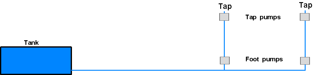
Note that you require one pump for each outlet and if the pumps are higher than the water tank a faulty valve in one pump may allow the other pump to suck in air rather than water out of the tank.
You would either use tap mounted OR foot pumps, not both together on one outlet.
Electric Pump Systems
Once you decide to go for electric pumping, even on a simple system, it is worth using "plumbers" pipe and fittings. This will ensure that it is easy to extend and improve. There is no reason not to use push fit plastic pipes and fittings but please, please make sure that you cut the pipe with a proper plastic pipe cutter. If you use a saw the jagged end can cut the rubber O-rings in the fitting and cause a leak. You can use compression fittings on the plastic pipe as long as you also use an insert to strengthen the wall. I would only do this if I had to make a joint with existing copper pipe.
Plastic pipe is far less likely to crack when water freezes than copper tube.
Always try to run the pipes in a position that you can get at once the boat has been fitted out – its just plain crazy to run water pipes through the bilges and then screw floor boards down and build furniture on top of the floor.
************** IMPORTANT ***************
At this point it is vital that you understand one basic physical fact:-
A gas (air) is compressible, water should be considered incompressible.
This has ramifications for various parts of the water system, not least in respect of how "high tech" the pump you will buy is.
This is why when the water freezes the expanding ice splits pipes. It also means that (in theory because the pipes etc. do give a little) as you turn the pump on the pressure is zero, one pump stroke of a few cc of water and the pressure will rise to an infinite degree. More about this later – see Accumulator or Expansion Vessel.
Once you decide to use electric pumping you must first decide what sort of pump you want to use:-
Centrifugal pump
This type of pump is probably now obsolescent. It works like the engine water pump described in the cooling system section.
Advantages
High output volume.
May have a built in accumulator (see later)
Disadvantages
Must have a separate Non Return Valve because it has no valves of its own.
Limited maximum pressure (not normally a problem).
Impeller can block with scale etc. so needs dismantling and cleaning at (say) 5-year intervals.
Rubber impeller pump (Jabsco water puppy etc.)
This type is an electrically driven version of the Jabsco raw water pump described in the cooling system section. It may well be supplied as a "pack" with an accumulator and pressure switch built into one unit.
Advantages
Easy availability of spares.
Same maintenance as the raw water pump.
Disadvantages
Limited maximum pressure.
Frequent impeller changing required because of wear.
Requires frost protection measures.
Requires a separate non-return valve, especially when worn.
Diaphragm pump
The working principle is shown below:
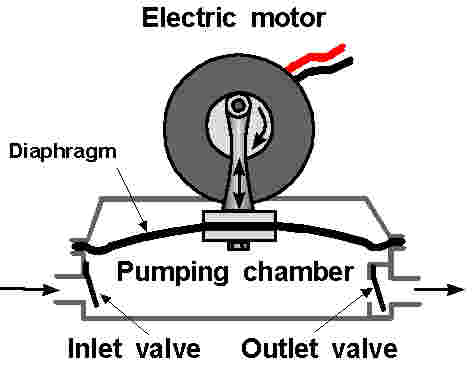
As the motor spins the diaphragm is pulled up and down. When the diaphragm is pulled up the water is drawn in, opening the inlet valve and closing the outlet valve. As the diaphragm is pushed down the water is forced out, closing the inlet valve and opening the outlet valve.
Please note that modern pumps may well have three smaller diaphragms driven by a wobble plate on the motor shaft. This just gives a smoother output, but the way they work is the same.
There have been several instances where stripping this type of pump to clear the valves has resulted in incurable water leaks.
Advantages
Long life.
High maximum pressure
Valves should pass hairs and grit etc.
Valves should be self-cleaning.
No non-return valve required.
Disadvantages
Requires frost protection measures.
Tend to leak if stripped for valve cleaning (plastic bodied ones)
The next thing to decide is if you want an automatic system or a manually switched one. If a manually switched one will do the job, then the system is very simple as shown below.
A Manually Switched System
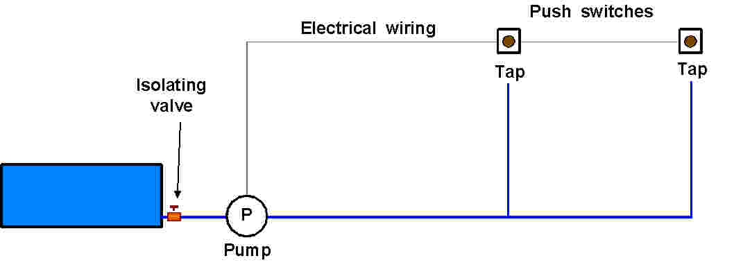
This system can use any type of pump and does not require any non-return valves.
The isolating valve is fitted as close to the tank as possible so the pump and other parts can be removed for maintenance without having to drain the tank.
It can be used for hot & cold systems, but it’s a bit of a problem if you fit a shower because the switches have to be push buttons if you do not want to burn the pump motor out.
It is a good system to use as a building block when improving manual systems when cash is tight.
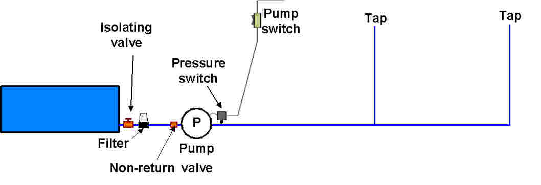
Pressure Switch Systems
Most boats will use a pressurised system using a pressure switch to turn the pump on when pressure drops in the system, and off when it reaches a pre-determined level. They only need one switch, but in my view using two way switching like the landing light at home prevents disturbed nights. This allows you to put a switch in both the galley and toilet compartment so the pump is only turned on at night when it is needed (this method of switching is not discussed in these notes).
Advantages
Is used just like the taps at home.
Does not require push buttons to be held in whilst using water.
Disadvantages
Tends to pulse the pressure.
The slightest leak causes the pump to run at intervals.
Back leakage through valves causes the pump to run at intervals
Contracting (cooling) hot water causes the pump to run.
Noisy in the quiet of night.
Requires frost protection measures.
Pressure Switch
These are best though of as a "black box". Some pumps are supplied with them built in/on. In this case one might have to puncture or remove a label to get at the pressure adjusting screw and that might invalidate the pump warrantee.
If a separate pressure switch is used (as shown) it can be adjusted at will and also it allows one to use "modern pumps" that simply have suffered pressure switch failure.
OPERATING PRESSURE
The higher the pressure the pump has to work against, the greater the current consumption. The higher the pressure the more strain there is on the system components. It is probably best to set the pressure to the minimum that still gives an adequate flow from the taps. However, if you are using an "instant gas" water heater the pressure would need to be set to ensure the water is heated to a sufficient temperature irrespective of flow from taps. In most cases somewhere between 10 and 20 psi will be more than adequate.
Here is the simplest diagram.
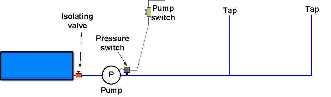
Operation
When the pump is turned on it pumps against the closed taps, this causes a rapid pressure rise and when the pressure reaches the setting of the pressure switch the motor is turned off.
If ANYTHING causes the pressure to fall the motor is turned back on. This is usually in response to the use of water, but may just as well be caused by some form of leak or cooling and thus contracting water in any stored hot water.
If the pump output is not matched to the tap flow the pump is likely to pulse on and off whilst the water is running. This is avoided on some modern pumps that are fitted with pressure sensing electronic speed control. Despite the manufacturer of this type of pump’s apparent statement that they can redefine the laws of physics, these pumps will still run if anything causes the pressure in the system to fall.
Although the pulsing with the taps on is not desirable for reasons of motor life and electrical consumption, in practice it does not seem to be a major issue in most cases.
All the above show that anything that causes the pressure to leak away would cause the pump to run at intervals, to this end I introduce two more items in the interest of a less intrusive and more fault tolerant system.
The new diagram is below:
Strainer or filter
These are often sold as "bilge pump strainers", ensure that you can get at the strainer for routine cleaning (once a year or so).
Its purpose is to try to remove any particles that could hold a valve partially open or damage/block the pump mechanism.
Non-return valve
If the pump is not fitted with a separate non-return valve I always fit one just before the pump. This ensures that any back leakage from a worn pump or internal valve is trapped on the pressure side of the system so the pump does not run at intervals. This builds redundancy into the system leading to greater reliability. A simple NRV from a plumbers’ merchant is all that is required.
So far we have built a system that should be tolerant of back leakage, but not of slight weeps and dripping taps (we all know how well children can turn taps off!). To overcome that we need another unit, and this will also go some way to preventing the pump pulsing if it is not matched to water flow very well. The new item is an accumulator or pressure vessel as shown on the next page.
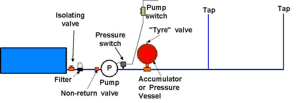
Accumulator or Pressure Vessel
These are simply a way of storing some water under pressure so that if a leak develops or if cooling hot water contracts there is a store of water ready to make up for the loss.
There are two basic types:
Without Diaphragm
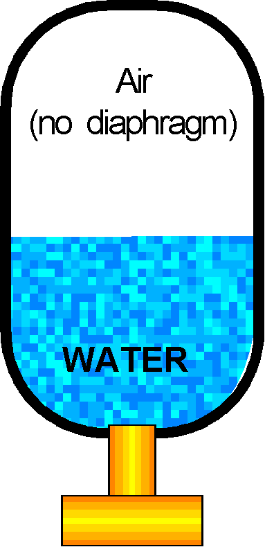 This type is a simple
metal or plastic container with a water inlet/outlet at the bottom.
This type is a simple
metal or plastic container with a water inlet/outlet at the bottom.
As water pressure rises the air in the top of the accumulator is compressed, allowing the water level inside to rise.
As water pressure falls the air pressure asserts itself, forcing water out of the container. This prolongs the time that water under pressure is available.
IMPORTANT NOTES:-
Always mount and keep this type of accumulator upright so the air cannot escape.
Periodically remove from the system and "shake" all water out. This replenishes the air "bubble"
The internal pressure
cannot be controlled.
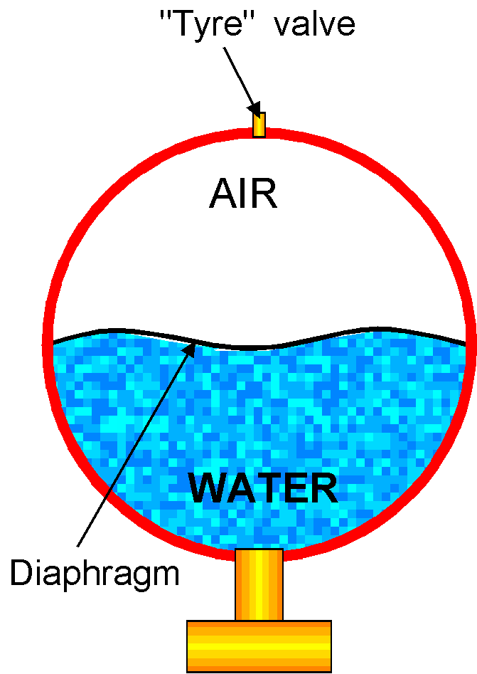 With
Diaphragm
With
Diaphragm
This type has a rubber diaphragm to separate the water and air. A car type tyre valve allows the adjustment and replenishment of the air. In operation it is very similar to the non-diaphragm type, but routine maintenance is easier and it allows the testing of water system pressure with only a tyre pressure gauge.
IMPORTANT NOTES
Pressurise air to about half the maximum system pressure.
Check the air pressure with no pressure in the system at least once a year.
Initial pressurisation
Pressurise to about 10psi with no pressure in the system.
Run system up to pressure and re-check pressure. This is normally your water cut-out pressure, so run all the water out of the system and reset the air pressure to about half the reading obtained.
Pressurise system and recheck. Repeat the above if the reading is not twice the initial pressure.
Operation of the system diagram above
As the system pressure rises the air in the accumulator is compressed and acts a bit like a big spring pushing down on the water.
Once the pump’s pressure switch turns off, any slight leak through a valve, tap, joint or contracting hot water will cause the air to push water out and virtually maintain pressure so the pump does not cycle (that is keep turning on and off) when no water is being used.
A system without leaks with an accumulator fitted should keep the pump turned off all night unless a hot water system is involved.
WATER HAMMER
Water hammer is a juddering or hammering sound that the water system produces when a tap is turned off.
This is caused when a moving pipe full of water is suddenly prevented from flowing AND some form of "spring" is in the system that allows the moving water to compress it. It then springs back and pushes the water back. The water in the pipe may bounce back and forth opening and closing valves, and causing the noise.
Air bubbles trapped in parts of the pipework or insecurely clipped pipes often cause water hammer. Sometimes the accumulator may cause it, but fitting one may also stop it.
It is probably best not to site the accumulator at the far end of pipe runs (from the pump).
Sometimes simply reducing the pump cut-out pressure is all that is needed – in any case most of you will be operating your boat’s water system at a far higher pressure than the one at home.
HOT WATER
The heat for the domestic hot water can be obtained from:
It is likely that problems with codes of practice allowing a competent person to fit an instant gas heater are such that they may be virtually impossible to replace. All I will say is just prolong the life of an existing appliance by draining the diaphragm chamber every winter to prevent frost damage.
All other systems will use a calorifier as illustrated below
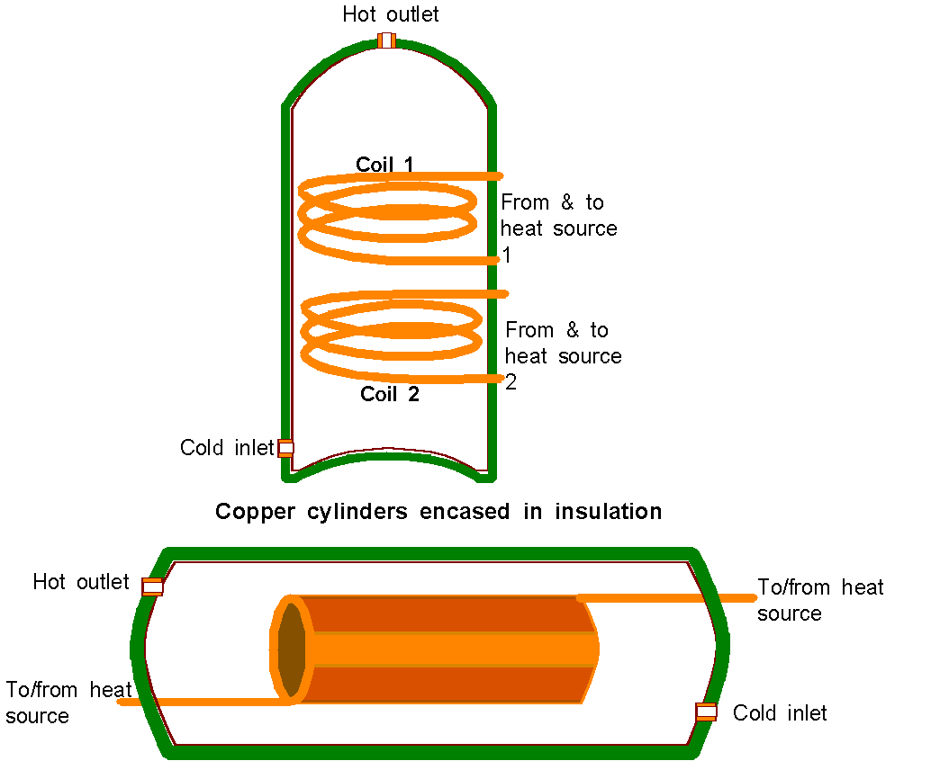
This diagram shows both a vertical and horizontal calorifier. Both work in the same way in that hot water is passed around a coil of copper tube or between the walls of a twin wall copper cylinder to heat the domestic water.
The vertical ones look like ordinary indirect hot water cylinders, but they are much stronger to cope with the higher pressures we tend to use. Often the horizontal ones are cased in plastic or metal casings and may have a number of sophisticated extras – at a price!
Both should be available with one or two coils. Twin coil ones are used if you want to heat from both the engine and some form of stove or boiler.
Expect a calorifier to be supplied with a pressure relief valve (more later).
Operation
Hot water from one source passes through one of the coils/cylinders and thus heats the water. If another source is to be used another coil/cylinder is utilised.
Thick insulation should keep the water hot for a long time after the heat has stopped being supplied.
Connecting to the engine
Check with the engine manufacturer/mariniser to find out where the hoses should be connected. If the engine is also used in a vehicle, tractor, digger etc. you could connect the calorifier up as if it was the cab heater.
It is often difficult to fit a calorifier to a wet exhaust, direct cooled engine – if you intend to do this seek very experienced help.
Often you will find a blanking plug in the cylinder head. This would be the hot water take off point.
A "T" into the main cold return close to the engine water pump often connects the return pipe.
Keep all hoses below the cooling header tank level and horizontal or with downward slopes away from the engine if at all possible – it helps minimise air locks.
When the engine-cooling thermostat opens it is possible for water flow through the calorifier to stop because heat exchanger/skin tank/keel cooler provides an easier path. To minimise this risk connect the HOT (away from the engine) pipe to the higher calorifier "coil" connection and the return to the lower one. Try to ensure both connections run horizontally at the calorifier end to prevent thermo-siphoning of water from the coil, backwards through the engine once the engine has been turned off.
If you find that the engine room calorifier pipes/hoses are still hot some time after turning the engine off and only cool water in the morning it will be because of thermo-siphoning. The best thing to try is swapping the upper and lower connections over. This usually cures it, but you might lose calorifier operation when the engine thermostat is open – only experimentation will tell.
From now on I illustrate a vertical calorifier, but the use of a horizontal one is similar. The diagram is illustrated below.
SIMPLE OPERATION
The pump fills all the system, including the calorifier and the water in the calorifier is heated, so when a hot tap is opened, hot water flows from the calorifier to the hot taps.
Complications
Now basic physics conspires to complicate matters. We look at these items now.
Expansion of water when heated.
My I am told that we must expect the water in the calorifier to expand by about 5% when heated. This means we must allow for about an extra 2 litres or half a gallon of expanded water between cold and hot on a 10 gallon calorifier.
If the system above (and some are like this) did not have an accumulator fitted all that extra water would do is to increase the pressure in the calorifier to a massive extent. As it is, the pressure will still rise.
The expansion gives rise to two problems:
This is why the accumulator is often fitted in the cold pipe, close to the calorifier. In theory the hot water would then force itself back into the accumulator, but the accumulator could still force hot water to a cold tap.
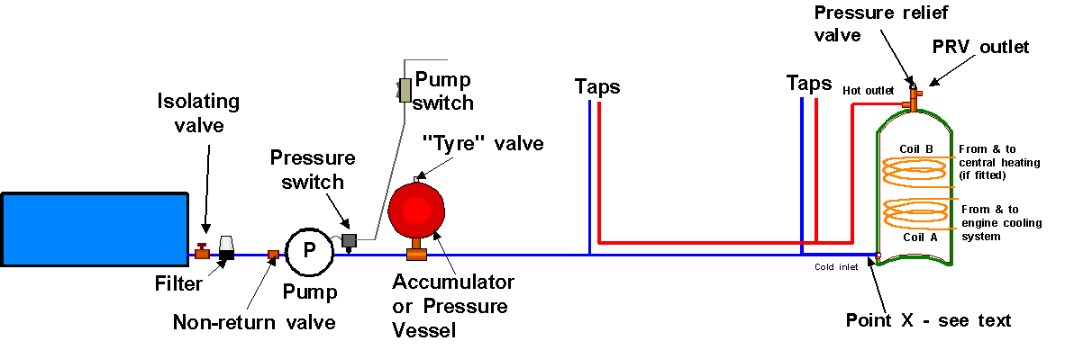
Point X
Another NRV (non-return valve) is often fitted here. This will prevent any hot water working back to a cold tap, but it will ensure a certain loss of water via the Pressure Relief Valve (PRV) - more later. Sometimes the accumulator or a second accumulator is fitted between the NRV and the calorifier, but if you do this the accumulator will not have any effect on pressure falls in the cold water system.
As long as the distance between the closest cold tap supply T and the calorifier is longer than the "hot water expansion" I tend not to use a NRV here, but on short boats or mid-engine rooms this is often not possible.
If a NRV is fitted here it will not be possible to fit all the water supplies "moving" parts in one place – again more later.
The calorifier drain point
The calorifier may have to be drained as part of winterisation. If the calorifier is not mounted on the cabin sole/floorboard then one can simply undo the cold water inlet union and drain into the bilge, however on many narrow boats this would result in ruining the carpet.
If the calorifier is located on the floor I would advise fitting a T at the inlet, so you can also fit a valve and connector for a piece of hose. This will allow the use of a drill pump to drain the calorifier without wetting the floor-covering etc.
When draining the calorifier you will probably have to loosen the top connection to let air in.
Pressure relief valve
Any cold or warm water in the calorifier will expand when heated thus a combination of the taps being turned off and any NRV or pump valve in the system will trap this expanding water.
Even if an accumulator is fitted the expanding water will bring about a pressure rise greater than the calorifier is designed to cope with. Vertical ones will first turn their bottoms from concave to convex – and then split. Horizontal ones just split.
To prevent this a Pressure Relief Valve (PRV) is usually fitted into the top, hot outlet of the calorifier. This should have a hose on it that vents excess water somewhere, the somewhere may be:-
Out through a skin fitting
Into the engine bilge
Into the accommodation bilge
Into the gas tank (rank bad practice).
Every time the water is heated and the pressure rises you get spurts of water from this hose. This is normal and one should not worry about it unless it is leaking all the time.
Continual leaks from PRV
If the PRV drain is leaking all the time it indicates one of three faults:-
Pump pressure switch failed or set too high.
Leaky PRV valve seat.
Faulty PRV
The latter is not that common.
The PRV Knob
The PRV normally has a plastic knob on top. This looks as if it is some form of adjustment. In fact it is a device that lifts the valve off its seating every time you turn it and it clicks.
If the pump keeps running and there is a constant leak from the PRV drain hose it may well be caused by scale caught on the valve seat.
Twist the knob a few times with the pump on to try to flush the scale from the seat.
PRVs are not normally adjustable.
Always fit a PRV with a lower pressure rating than the calorifier – typically between 2 and 2.5 bar (30 to 37 psi).
Alternative to a PRV
At one time a simple vehicle cooling system expansion tank with a 21psi radiator cap was a popular way of avoiding using a PRV. There is nothing wrong with this as long as the cap is kept in good condition.
HOT WATER DANGERS
The water in the calorifier fed from a modern engine may well end up at well over 90 degrees. This may not be a danger to adults who are aware, but it may be a danger to children, old people, and everyone in absent moments.
Seriously consider fitting a thermostatic mixing valve between the cold water inlet and hot water outlet to limit the water temperature. The expensive, horizontal calorifiers may have one already fitted, but any plumber’s merchant (or Screwfix) can supply a suitable unit.
Rationalising the system
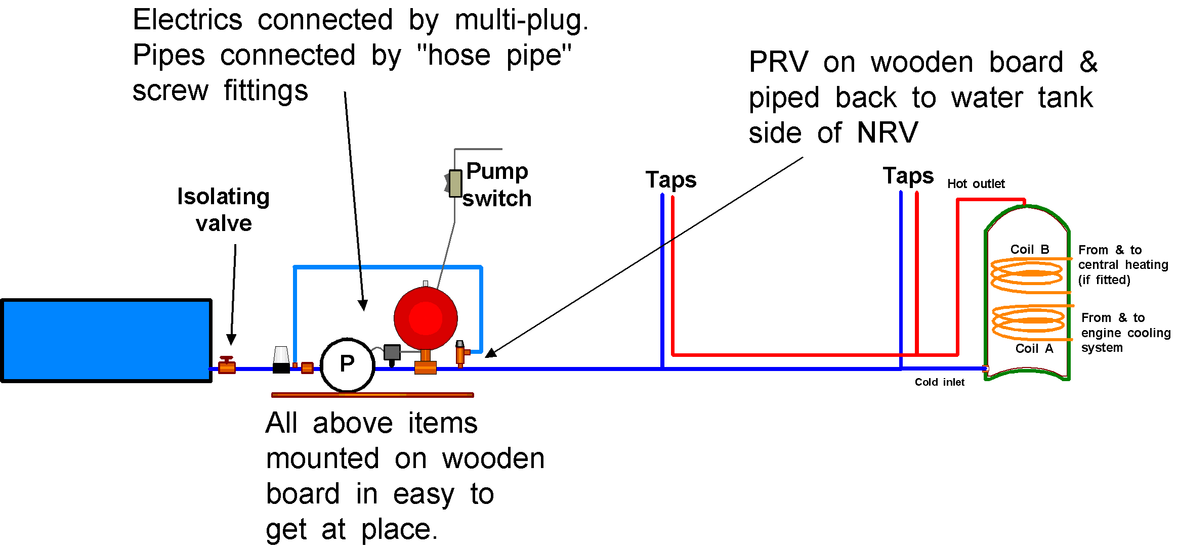
You are likely to find that the boat builder has seen fit to "sprinkle" the various parts throughout the boat. This is fine as long as a search can be effectively drained for winter and you know where they all are. After much consideration I have modified my system as shown below.
Now when the system is drained for the winter the board with all those expensive items can be easily removed and taken home in the warm. It also makes fault finding simpler because most of the parts are in one place. If the PRV leaks however you will not have a stream of water to show you – all that you will sense is that the pump keeps running, but it saves water.
Danger
There is one danger in doing this; that is that hot water might come from the cold tap closest to the calorifier.
Extra use of a calorifier system
If you have a pumped central heating system fitted to a twin coils calorifier and the all too common undersized skin tank, turning the central heating pump on can often mitigate engine overheating under high power. This has the effect of transferring engine heat to the radiator system and thus cooling the engine – in the summer !!
On single coil systems leaving a hot tap running may also have a similar effect, but you will lose a lot of domestic water.
SERVICING THE WATER TANK
Mild steel tanks will need their covers removing, cleaning, and re-blacking every few years (rather you than me). Just make sure that you use a blacking that states its suitable for potable water, let it dry really well, then fill and flush a few times before use.
Stainless steel & Plastic tanks may harbour all sorts of things, so I suspect that most people make some sort of attempt to sterilise them. This can be a bit of a hit & miss affair if you do not know how much water they hold.
You can buy special marine tank sterilising products, but things like beer pipe cleaner, Milton, non-thick or perfumed bleach, and wine sterilising materials will all probably do. Fill the empty tank with some water, then the correct amount of steriliser for the tank capacity, and top up with water. Run each tap until you can smell/taste the steriliser. Leave overnight or for a few days. Pump out tank via the taps, flush and refill. Any smell or taint will quickly go.
DRINKING WATER FILTERS
Hire boats are required to have one of these fitted to supply "pure" drinking water. This is usually a small tap and swan neck outlet at the sink. The filter unit is usually under the sink, in the sink unit.
There is absolutely nothing wrong with these units, but I would never have one with a ceramic filter because:
If you are going to use one, please make sure you change the filter frequently. Some years ago Thames Water did some tests on water filters in the home and they found that the majority were so old they were supplying dirtier water than ordinary tap water – they may well have had other agendas, but I can see this would tend to be correct.
Perhaps a filter jug with the readily available elements might be the safest thing to use.
SHOWERS
There are two considerations with showers:
Mixing valves
Basically fit what you like. At least the water pressure is normally such that you get a power shower for free.
If you fit a non-thermostatic valve you will get temperature variations if someone else turns another tap on, but they are cheap.
There is no routine maintenance applicable to an engineering document.
Winterisation
Either remove the valve and take it home or remove its face or ALL pipes to ensure there is no water inside to freeze. This is vital on £200 thermostatic mixers.
Shower Pumps
You have a choice of three types of electric pump:
Electric diaphragm pumps:
will run dry for quite a time before damage ensues.
have self-cleaning valves (for hair and such like)
be very noisy for those moored alongside you.
You can control these by a switch that you turn on before showering and turn off when you have done because they are unlikely to damage themselves, but if you are thinking about regular use in a marina they might not be very sociable. As long as nothing large or sticky is pumped there should be minimal maintenance required.
Centrifugal pumps in a sump are basically an electric bilge pump inside a plastic case that is supposed to be water tight. They will run dry virtually indefinitely, so can be left on all the time you are showering.
You do need to get the wires out and you do need to get the pump out – often the cases are not exactly watertight, so if you have one of these and you find a constantly wet bilge, this is your first point of inspection.
I know from experience that the easiest thing to block this type of pump is long strands of stuff – like hair. This will require pump removal and impeller cleaning.
They may well make sense on sea going craft where all grey water will normally be discharged overboard, but in certain countries may have to be pumped into grey water tanks, but I have reservations about this type of unit.
Jabsco type, this impeller type of pump must not run dry because this will quickly damage the impeller. To help prevent this a little care is required during installation. Also you can only use a push button type of switch so the pump stops when you release the button. It will, however, deal with hair quite well.
The routine maintenance is to remove and inspect/change the
impeller every couple, of years or so AND to drain it/remove the impeller for the winter.
It should be mounted and piped as shown below.
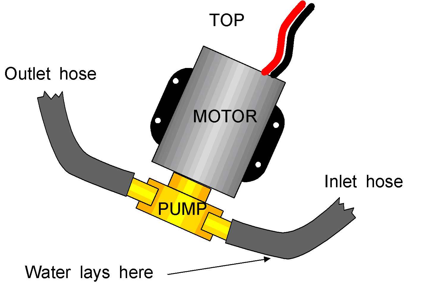
The pump is mounted just off the vertical so that a leaking water seal will not fill the motor with water and also to ensure water will always lie at the inlet to the pump. This will ensure the impeller is water lubricated if someone holds the switch on without water in the shower. By having the pump below the hull outlet, some water will always run back down into the pump.
Fault finding
If water either runs back into the shower tray from the drain or if pumping is sluggish, expect either a worn pump body/cover plate or (more likely) a worn impeller.
WINTERISING
This has been mentioned in the text, but it is up to the individual to weigh up the risk of freezing and its likely cost against the time required to drain the system.
Live-aboards will rarely have to consider draining the system because they will be keeping both themselves and their pipes warm.
I would certainly advise that any boat that is wintered ashore be drained because there is no slightly warm water around the hull to help keep the internal temperature above freezing.
Boats with all copper pipework are far more likely to suffer freezing damage than those with plastic pipes are.
The alternative to draining is heating the boat. This is not likely to be viable unless you either have a shore line or the boat’s heating system does not use battery power AND is thermostatically controlled. Things like Alde boilers and Mikuni type diesel heaters may well flatten the batteries with their pumps etc. unless some form of battery charging can be provided, and as we are considering winter, I doubt solar panels will suffice.
I really cannot give any more advice here because it is all about guessing future weather.
|
|
||
| Back |
Home Index |