| Back | Home | Index | On |
Sooner or later you will be presented with instructions showing an electrical circuit as a series of symbols. These can be miniature, simple pictures that are fairly easy to understand or symbols drawn to one national/international standard or another.
To try to help you read these circuit diagrams some of the more common symbols are produced below.
 |
A single cell. On a boat this will give us about 2 volts, in a torch about 1.5 volts |
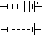 |
These are batteries of 6 cells. This is two methods of showing 12 volt batteries. |
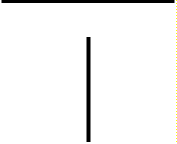 |
This is how conductors (pieces of wire) are shown. They should really only be drawn vertically or horizontally. |
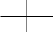 |
Conductors crossing each other, but not joining. Note there is no "dot". |
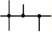 |
Conductors joining each other. Note the joint is shown as a dot. |
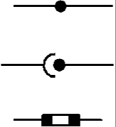 |
Various joints in wiring cables. Fixed Breakable (male-female) Breakable (bullet connector) |
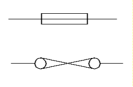 |
Two different symbols for fuses.
The bottom one is obsolete, but can still be found. They may also be used to show circuit breakers. |
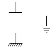 |
These symbols show "earths" where the negative cable is connected to a metal frame. Ideally these would never be seen on marine diagrams, but it is likely they may appear on the engine. |
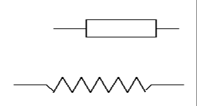 |
Resistors – only likely to be found on very old heater plug circuits. The lower one is obsolete. |
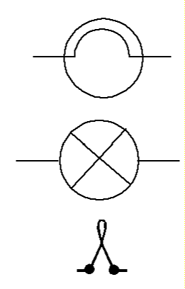 |
Various bulb symbols, they tend to
get interchanged, but:- Main illuminating bulb Pilot light (warning lamp/instrument illumination) Obsolete symbol |
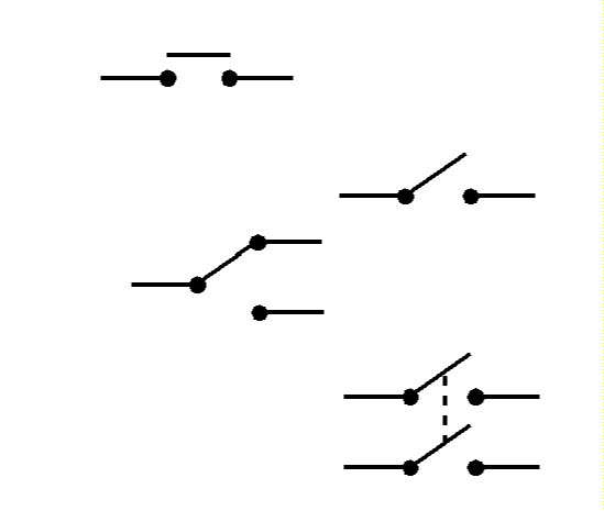 |
Various types of switch :- Push button (horn) Toggle switch (simple on-off) Change over (Bilge pump to automatic or run) Double pole |
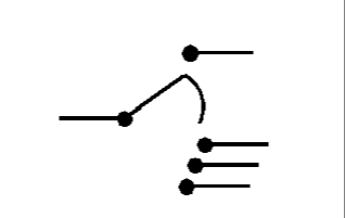 |
This is a special form of switch
that can turn more than one thing on. This one is an ignition switch shown in the off
position. Reading from the top the positions are (Anti-clockwise) Stop solenoid OFF (Clockwise) Instruments + Glow plugs + Starter |
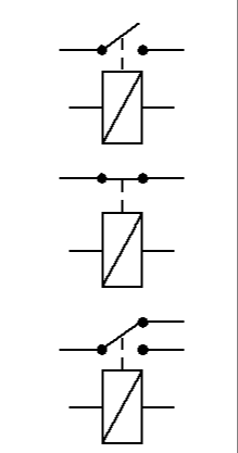 |
Relays – the rectangle is an
electro-magnet, with a switch of some sort above it. These allow us to use small/cheap
switches yet reliably switch large currents. Types shown:- Pull to make (normal sort – split charge etc) Pull to break Change over |
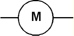 |
A Motor – it does not show what sort, but we will assume it a DC one. |
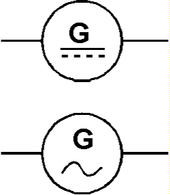 |
Generators – the first one
has a DC output, so could be the alternator. The parallel solid & dotted lines show
this. The second one is AC, so it could be a built in mains generator. The wavy line shows this. Ideally they would both have their voltages written on the symbol. |
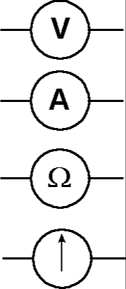 |
Various forms of meter, either
hand held or built in. From the top:- Voltmeter Ammeter Ohmmeter The bottom one is something known as a galvanometer, but this symbol often is used to show "some kind of gauge", so it could be a fuel or temperature gauge. |
 |
Diodes – electricity can only
flow in the direction of the arrowhead. Ordinary diode – in the alternator & in split charging diodes. LED - Light Emitting Diode – used as warning indicators on electronic equipment. Zener Diode – ignore this, they are inside alternators measuring voltage and protecting the electronics from damage when the battery is disconnect whilst the engine is running. At a pre-determined voltage allows electricity to flow "backwards" through the arrowhead. |
Circuits in this book
To try to make things as easy as possible, a lot of this book will use,
non-standard pictograms instead of some circuit symbols. These are probably easier to
understand for the engine electrical equipment.
If one tries to understand all the boats wiring at once mistakes are likely to be made because of the complexity of it all, however if each circuit is taken, one at a time, and understood, the whole thing becomes much easier to handle.
A basic circuit consists of an electricity supply (the battery in our case), a length of "go-to" cable, a switch (unless you want the thing to work all the time), the load (a bulb, motor, TV etc), and a length of "back-from" cable.
This would work, but if the load developed a fault the wiring could catch fire, so to minimise this danger a fuse or circuit breaker is fitted as close to the battery as practicable. If a fault did develop that would cause a fire, the fuse will blow, or the circuit breaker trip, cutting off the supply of electricity to the circuit.
The basic domestic circuit looks like this.
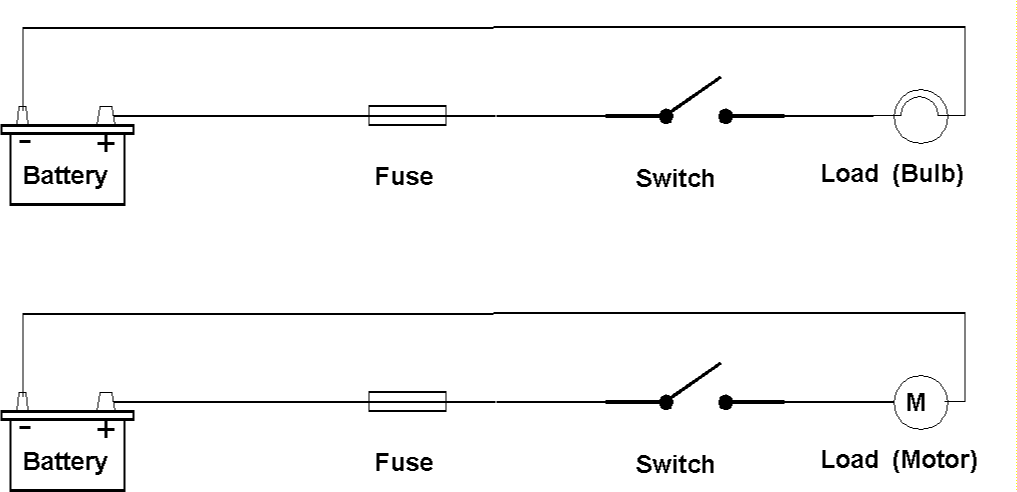
It really does not matter what the load is, the basic circuit is always the same.
You can get clever and add relays to allow you to switch things like pumps on and off remotely.
You can put the switch in the negative side of the circuit – its very bad practice to do this because if you make a habit of it, one day you will do the same on a mains circuit, and that will leave the light bulb socket with live mains at it even when the switch is turned off. You can do it – but don’t.
Modifying for the Boat Safety Scheme
The boat safety scheme requires a battery master switch, so this is added thus:-
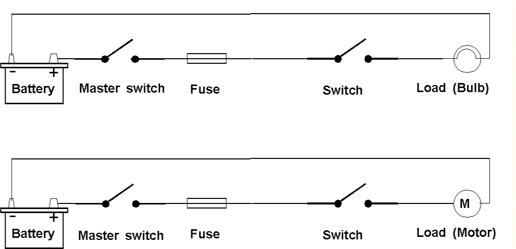
We have just added the master switch – again some people put it in the negative wire, but your lecturer much prefers it in the positive.
Obviously you do not need two individual batteries and two master switches for the domestic circuits, so parts of the above circuits can be combined, as shown below:-
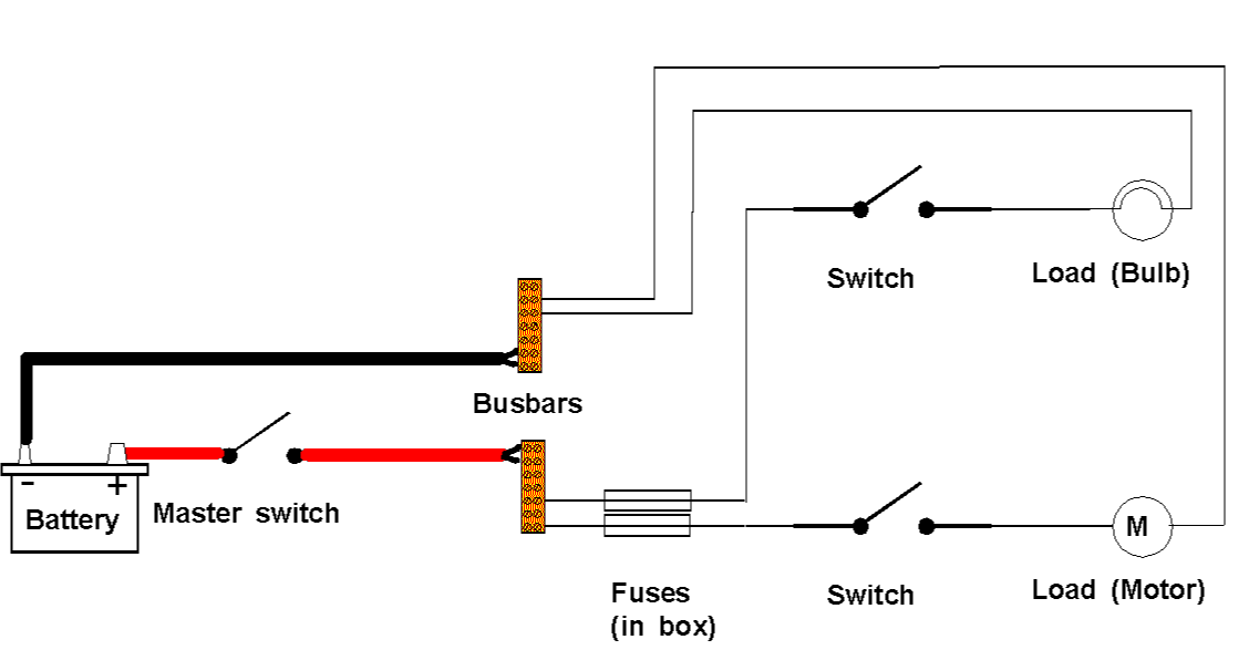
The above diagram should suit most domestic battery systems – just keep adding fuses and circuits to the busbars.
Busbars
Chunks of tinned copper or brass that are used to allow the connection of many different wires. Ensure they are electrically insulated from the boat.
A modern fuse/circuit breaker panel is likely to have busbars inside it, otherwise they are available from any electrical supplier, they might not be tinned, so would be subject to corrosion for sea work.
The bus-bars are connected to the battery by very heavy gauge cable. If it is too thin it will get hot in use and cause a loss of voltage to the loads (the things you want to run). Thus the little Ys where the battery cable strands have been split where they join the busbars.
The Heavy Gauge Cable
Do not expend too much effort selecting this cable. It needs to be as thick as you can afford and run through the boat. If you spend a bit extra here you will make it far easier to add extra loads in the future.
The Domestic Master Switch
In most cases this can be the same rating as your engine one. Using two switches allows you to turn the engine one off for safety during maintenance, yet still provide power for the domestic equipment – you can get tea made for you because you have not turned the water pump off whilst changing an alternator belt!
If you are using a large inverter you must calculate the current required and choose a master switch accordingly.
Do not stint on the specification of the master switches – choose brand names – no-name cheapies are unreliable and could cause a fire!
Bow-thruster & Winch Circuits
These circuits draw a very heavy current, so it would be a good idea to consider providing a totally separate battery and circuit for these items.
The circuits would be exactly as shown above, except the loads would be the bow-thruster or winch and their control gear. Where possible you would NOT use busbars because each joint would create volt drop, so direct wiring would be advised.
If you are running these from either the engine or domestic batteries it is vital to take account of their load when selecting the master switch.
Before we can select suitable fuses/circuit breakers or cable we must be able to calculate the current they will be required to supply.
Before you can specify the correct fuse, or buy the correct cable you MUST find out how much current will be flowing around the circuit.
Some domestic items like pumps will be rated (the numbers will be in a plate or stick on label) in amps. You do not have to do anything to this value.
Many things like lights are rated in Watts.
Unfortunately you need to do a simple sum to find the current flow form a wattage.
The formula is
So for a 21 watt lamp you would give:
(I would take that as 2 amps to build in a bit of safety margin).
Some things are known as inductive loads. The easiest way to sort it out is to consider anything that is not a filament lamp an inductive load – and you will not go far wrong. If it turns out that something was not an inductive load there will be no harm done, because any errors would be on the safe side. Inductive loads demand a much larger current flow to get them started, than they do when they are running, so this must be taken into account when specifying fuses/circuit breakers.
For simplicity increase the current calculated for an inductive load by 20% when specifying cables. (This is a massive generalisation, but it is not unreasonable for the amateur).
If the lamp above were a 21 watt fluorescent the calculation would be thus:
21
¸ 12 = 1.751.75
¸ 100 x 120 = 2.1 ampsThis really would make little difference to a lamp circuit – especially as I said that I would have taken the current flow to be 2 amps anyway, but on a 10 amp pump the calculation would give 12 amps.
If you are wiring TO an inverter take the rated output of the inverter as the watts and 10 as the voltage. This builds in an allowance for the inefficiency of the inverter.
The inverter is what is known as an inductive load so increase the currant by 20% thus:
1500 watts
¸ 10 = 150150
¸ 100 x 120 = 180 amps