| Back | Home | Index | On |
TWIN ALTERNATOR SYSTEMS
When an engine is fitted with twin alternators and one is dedicated to each battery bank the first thing to say is that in most cases the engine bank alternator spends most of its time doing very little because the current taken out in starting is quickly put back. We will look how this can be turned to our advantage though.
There is one complicating factor in trying to wire a twin alternator system and that relates to the fact that most alternators require a very small amount of current to be supplied to start them charging. If this is not provided we are told that the alternator will not "self energise". In reality they often do, but it requires the engine to be revved up, sometimes considerably. On a single alternator system this small current is supplied via the warning lamp. The bulb’s resistance is used to prevent the batteries being flattened if the "ignition" switch is left on over night. A wire without the switch and bulb in circuit could be used, but it would draw between 3 and 4 amps all the time the engine was stationary
With two alternators it would be inadvisable try to energise the domestic alternator from the "ignition" switch because the current would not have a return path (because the negatives of both battery banks would not be linked) and it would introduce a greater likelihood of the different voltages on each battery bank illuminating the warning lamp.
This diagram shows how to solve the problem.
Operation
When the "ignition" switch is turned on both the engine warning lamp and the domestic energisation relay are supplied with current. The relay closes and supplies current to the domestic alternator warning lamp and thus energises the domestic alternator.
The relay coil is part of the engine electrical system whilst the contact are part of the domestic system.
If you have a split 12/24 volt system with one battery bank being a 24 volt bank and the other 12 volts then exactly the same diagram and operation applies. Just write 12 and 24 on the respective batteries on the diagram.
Just make sure that if you intend feeding the coil with 24 volts that it is suitably rated.
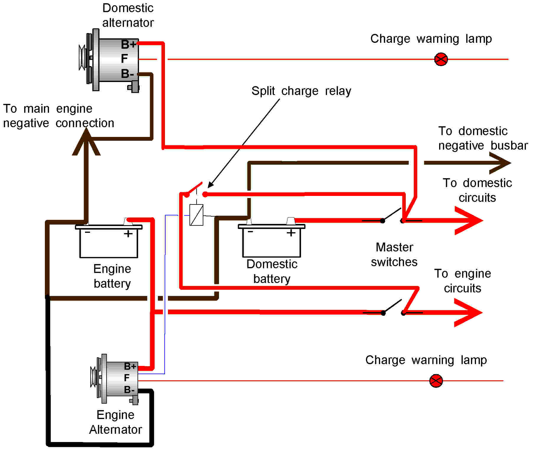
USING WASTED ENGINE ALTERNATOR CAPACITY
By employing a split charge relay to link both battery systems while the alternator is charging the output from both alternators can be used to maximise the charging current. However remember that the greater the charging current in relation to battery capacity the shorter the battery’s life. In many cases this will be considered an acceptable compromise is seeking to reduce the time required to recharge the domestic batteries. It can also help in powering large inverters when the engine is running.
The diagram is shown on the next page.
Operation
As these systems use modern alternators the alternators should be equipped with an auxiliary terminal that only becomes live when the alternator is charging. This is used to energise a split charge relay that connects both alternators in parallel so both alternators charge both batteries. The effect is to increase the charge rate for the domestic battery bank.
Both battery bank negatives are linked with heavy cable so the electricity can find its way back to the respective alternators.
*** WARNING ***
It is vital to ensure the wiring and relay are adequate.
Always err on the side of caution and specify larger capacities than you think you need.
This diagram may not be BSS compliant, the one below is.