| Back | Home | Index | On |
So far you have worked out all the current flows required, specified the cables, fuses, batteries and alternator. You may also have run your domestic circuits that will be like a tree – lots of branching from the busbars.
Please think before you rip out all the boat’s wiring to start again. You are unlikely to have the diagrams supplied with all the equipment, and although the domestic items are usually straight forward, with just a positive and negative connection, the engine electrics are a different matter.
Disconnect the cable you are interested in from one end.
Connect a length of thin cable to this and then to the meter.
Probe likely terminals at the other end with the other meter lead until you hear the buzzer.
We will develop each major circuit in turn, starter, charging, instruments etc. The operation and fault finding will be covered in each section.
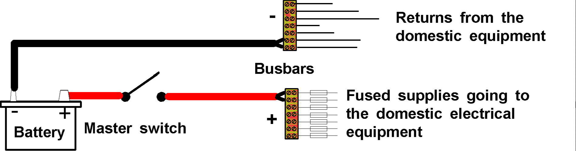
We start with the basic diagram:
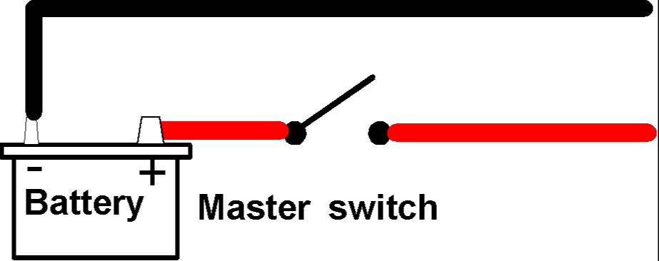 |
Battery, battery master switch and much heavier cables of about
40mm2, give serious thought to buying "extra flexible" because it may
make it easier to do neat cable runs and also reduce the strain on the terminals. For runs much over 2 metres you should do the voltdrop calculation. |
INSULATED RETURN & EARTH RETURN SYSTEMS
The above diagram and also the sections on domestic electrics show that we use a TWO WIRE or insulated return system on boats. This is the ideal, especially on metal boats because sundry connections to the metal hull (so the current can get back to battery negative is a recipe for corrosion).
Unfortunately most boats belonging to the target customer for this course will have engine electrical components that may look as if they are insulated return, but, in fact, are not.
They will probably have negative terminals on the starter and alternator, but if you look closely at them you will see they are just bolted into the metal body, rather than through insulated washers and bushes. The gauges, warning lamps and glow plugs are all likely to be earth return (one wire) circuits.
DO NOT WORRY ABOUT THIS. As long as you only have one negative connection to the engine and everything else "earths itself" to the engine, there should be minimal risk of corrosion.
To accomplish this we will connect the heavy battery negative lead to the starter negative terminal or to any suitable bolt or stud in the engine, and we will run another negative wire (say 28/0.30) between the engine battery negative and a negative busbar close to the instruments. Ideally the instruments will be mounted on an insulating board to keep their bodies away from the metal of the boat.
TO FUSE OR NOT TO FUSE (Engine Circuits)
As has been stated above, a fuse or circuit breaker is employed to protect the wiring from catching fire if a fault develops. All domestic circuits should be fused, but the engine circuits are somewhat different because some of them will be difficult to fuse reliably because of the exceptionally high currents they carry.
In automotive work we do not fuse circuits where a failed fuse would immediately cause a dangerous situation, so we tend not to fuse ignition circuits because if a fuse blew, the car would stop exactly where it is, so if its on a level crossing – hard luck. We risk a catastrophic fire as having a lower likelihood than a fuse blowing in a dangerous situation.
In marine use one could imagine that it could be safer to let a cable start to overheat and smoke, whilst still keeping the engine running to maintain control, until the boat can be brought to safety. It also may not be economic to include fuses in circuits that have their current flow limited by other means or that are only employed for short non-critical periods.
Many engine installations have no fuses whatsoever and they appear to be safe enough in use.
I would advise keeping the engine electric’s fuses/circuit breakers separate from the domestic panel to make isolation of specific fault areas easier. I would also advise that the engine electric’s fuse/circuit breaker panel is mounted close to the ignition switch/instruments and inside the accommodation. This should minimise dangers of corrosion. If fuses are to be used I think the modern "twin blade" type automotive fuses are likely to be the most reliable and easily available.
It is not really an ignition switch because the engine is probably a diesel, but the name sticks, so I will use it.
Just about all the engine electrics have something to do with the ignition switch, so we start there.
This switch has to pass quite high currents to things like the starter and glow plugs (if fitted), so again do not stint – buy brand names.
|
There is no law that says you must use an "all in one" switch, its just that most people do because the key gives them some sort of security (not a lot – see later, but some). There is no reason why you should not use push buttons of sufficient capacity for the starter and glow plug circuits if that is what you prefer to do. In that case you could also use a simple switch to turn the ignition on and off. | |
|
Note the selection of small and large terminals at the far end. THESE SHOULD BE LETTERED OR NUMBERED |
If you look at the terminal end of the ignition switch you will see a mixture of small and large terminal blades.
Some of the blades are joined by strips of brass or copper. Any terminals that are joined in such a way will all be turned on or off at the same time.
There will be two sizes, some about 6mm wide (the small ones) and some about 10mm wide.
The large terminals are the ones for high current like the supply, to the glow plugs and to the starter.
One of the first things to do is to find out which terminal should be connected to where. If the terminals are numbered or lettered it may help you, you might be given a diagram in the box.
If the switch has numbers, one hopes they accord with the DIN standard, some of which are set out below.
DIN terminal numbers
30 = Main supply from battery
31 = Negative
15 = Ignition/auxiliary feed
51 = Auxiliary feed
85 = To relay winding
86 = Relay winding negative (only on relays)
87 & 87a = Relay outputs
If it has letters the letter B usually indicates the feed from the battery.
In the absence of any markings you must test the switch, but first you need to know what the switch is intended to do. There are so many variations that it is impossible to give every possible combination, but some are shown in the table below.
Sprung or un-sprung |
OFF |
Un-sprung |
Spring back |
Spring back |
|
Switch type |
Anti-clock |
Clockwise |
|||
1 |
Off |
Auxiliaries |
|||
2 |
Off |
Auxiliaries |
Start |
||
3 |
Glow plugs |
Off |
Auxiliaries |
Start |
|
3 |
Off |
Auxiliaries |
Glow plugs |
Start |
|
5 |
Stop |
Off |
Auxiliaries |
Glow plugs |
Start |
6 |
Stop |
Off |
Auxiliaries |
Start |
|
Diagrams for each switch type
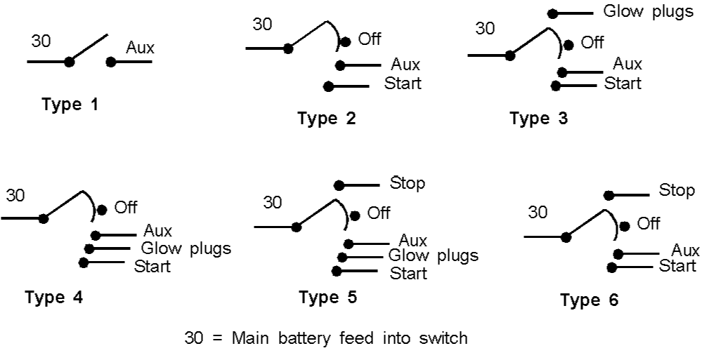
Note – the phrase switch type does not indicate any common standard, it only serves to identify the switches within this publication.
To identify switch terminals.
First we must identify the OFF position, so put key
in switch and feel each position and feel for the spring. Just two unsprung positions This is a simple on/off, type 1 switch. It will have just two groups of
terminals. One is the input from the battery, and the other (often paired up) is the
auxiliary feed. Two unsprung positions and one sprung back from clockwise As type 1, but the fully clockwise position is the start position. This is a
type two switch. Turn fully anticlockwise to the off position. Springs back from Anticlockwise, two unsprung and one
sprung back from clockwise Type three switch. Turn the key to the anticlockwise, unsprung position for
OFF. Two unsprung positions and two sprung back from clockwise Type four switch. Turn it fully anticlockwise for off. Three unsprung positions and two sprung back from
clockwise Type five switch. Turn it to the centre unsprung position for off. Three unsprung positions and one sprung back from
clockwise Type six switch. Turn to centre unsprung position for off. If you have a type 1 switch you can use either terminal/terminal group as the
main feed in, but I would advise using any grouped terminals as the output because it
gives you more connection points.
You should now have found all the terminals you need to connect the various
engine circuits. There is no service for the switch itself. Annually just check that all the terminals are secure and tight. The most likely circuits to fail within the switch are the glow plug/heat and
the starter circuit, although the test below can be used for any circuit. A reading of 0.25 volts or below may be taken as satisfactory. Repeat several times to ensure you do not get a "fluke" reading. A higher reading indicates a faulty switch that must be replaced. Before we can connect up the circuits we must look at Relays and Solenoids.
Some engines, especially older ones, use a special switch that makes contact when the engine oil pressure rises upon engine starting.
These are usually about 50mm in diameter and have TWO terminals on them (if it’s a single terminal it’s probably an electric oil pressure sender). This switch can be used to "turn the alternator on" or even turn all the engine warning lamps and gauges on. A live feed runs to the switch (via a fuse I hope) and the other terminal takes current to gauges etc.
Using a switch like this with an ignition switch prevents flat batteries if the ignition switch is left turned on with the engine stationary – an added complication in my view! It will also allow a diesel engine to be started with a simple push button and then turn on all the instruments – not very secure!
A relay consists of a coil of fine wire forming an electro-magnet and a set of switch contacts that are attracted to the magnet to make, break or changeover a circuit.
They are used to allow a small current to switch a much larger one. For example, glow plugs can draw over 75 amps (for a short while). You can feed this directly from the ignition switch, but that will tend to overheat the switch contacts and terminals, so the ignition switch usually controls a relay, and the relay turns the glow plugs on and off.
In the example above a thick wire from the battery, ideally it will be fused, but often is not, is connected to terminal 30. Terminal 87 is connected by another thick wire to the glow plugs.
Terminal 85 is fed, by a thin wire, from the ignition switch and terminal 86 is run back to the battery negative somehow.
Relay servicing
There is no servicing for a relay apart from checking its terminals are tight and secure on an annual basis.
Relay fault finding.
The maximum volt drop should be 0.25 volts. If its is much more, the relay needs replacing.
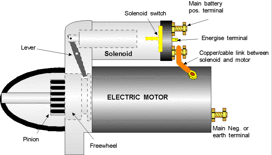
The solenoid is much the same as a relay in that it uses an electromagnet to move something, but this time the electromagnet is a lot larger and stronger and it slides a great chunk of iron about. Usually a spring pushes the iron back, once the magnetism has been turned off.
Some solenoids, like those on old car starter circuits, work as a giant, heavy duty relay. Others, like those actually mounted on the starters of modern cars and diesel engines, pull part of the starter about and also make an electrical contact like a relay.
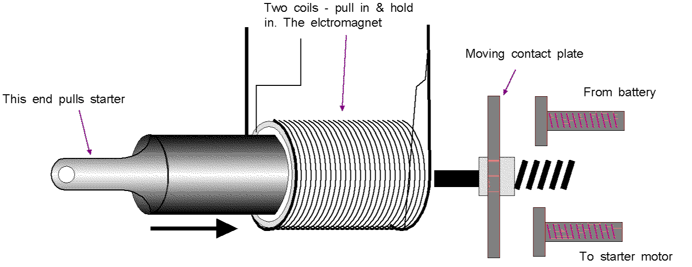
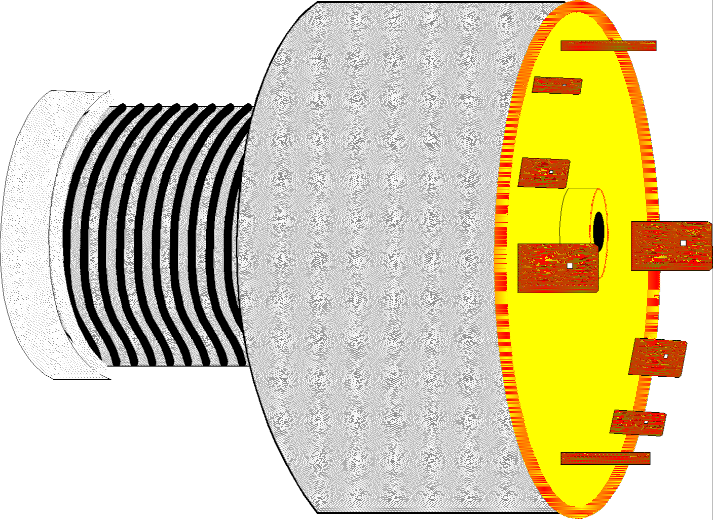
This diagram shows the inside of a diesel starter solenoid.
When the switch is turned to the start position, the electromagnet pulls the centre part to the right. This has two effects:
One of the coils is called the PULL IN coil because it is strong and initially pulls the centre part, and then gets turned off. The other coil, the HOLD IN coil, helps to do the pulling in and then just holds the solenoid in position until the current to the coil is turned off.
The only interest the two coils should have for ordinary boaters is because if one fails, then some odd symptoms can occur.
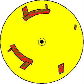
Simple Solenoids.
The simple starter solenoid is just a single, smaller coil, the moving centre iron section and the contact plate and contact bolts. It is usually mounted with the coil vertically.
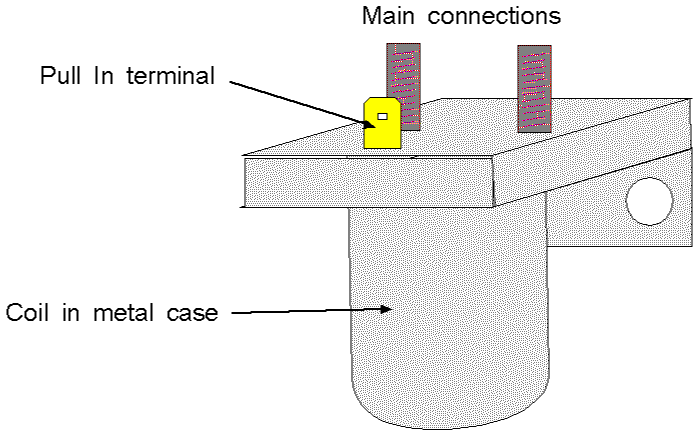
Some examples have a fully cylindrical appearance.
This one, with only one operating terminal needs the negative wire connected to the case – so do not mount it on a metal hull.
Many cars with automatic gearboxes used a solenoid with two operating terminals, one of these would be fine. Take care because some "two" terminal units use one of the terminals for feeding the car’s ignition system, so that type will not work with a fully insulated return.
Solenoid servicing
No service is required apart from ensuring the terminals are tight and secure on an annual basis.
Solenoid fault finding.
Readings outside the values indicate a faulty solenoid.
NOTE: Faultfinding without a meter is covered under the Starter Circuit.
The first thing to understand is that the starter motor draws an exceptionally high current. As it is first energised it will draw more than 180 amps – could be 600 amps or more on large engines, and then as it speeds up, the current drops to a lower value depending upon how hard it is to spin the engine.
There is absolutely no way we can reliably switch that level of current with a manual switch, so a solenoid must be used.
On the smaller engines the starters will be one of two types:-
Inertia starters – on petrol engines and a few diesels (Perkins 4-10x if I recall).
Pre-engage starters – Most diesels up to about 2 to 3 litres.
The larger engines may have Axial or Co-axial starters. They are just much larger than pre-engage starters, a different shape, and their "solenoid" is hidden from view. Their wiring is the same as the pre-engage units, but with terminals in a different place – 1 small to energise it, 1 large to supply with current, and possibly another large to connect to battery negative.
A typical pre-engage starter solenoid will draw about 30 amps with the axial and co-axial starters drawing more.
An inertia starter solenoid will draw rather less, but it is still quite a high load.
Do not stint on the size of the wire between the ignition switch and the solenoid. For normal runs of up to about 4 metres use 28/0.30 for inertial starter solenoids and 44/0.30 for pre-engage solenoids. I should point out that there are lots of boats operating with 20/0.30 cable supplying the pre-engage solenoids, but they are overloading the cable. This will cause it to heat up, but as it is only carrying current for a very short time this is often accepted.
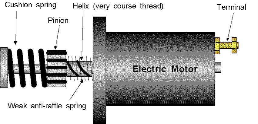
Operation
When the engine fires, the flywheel causes the pinion to rotate faster then the shaft, so it "screws itself" back along the shaft, out of mesh.
The Anti-rattle spring stops the pinion vibrating along the shaft whilst the engine is running and "pinging" off the flywheel teeth (occasional metallic "ping" from between engine and gearbox could mean that this spring has failed – it could also mean the gearbox drive plate is breaking up).
Starter servicing
There is very little the average owner can do.
On extended periods (say 5 years) remove starter and clean helix to make sure pinion is free running. Treat with a DRY lubricant if you want to (very light oil may be OK on a boat, but it would clog up with clutch dust on a car!)
Ensure the cushion spring is intact and has not shortened (it should be difficult to turn on the shaft).
Visually inspect the pinion and flywheel teeth for wear – replace if too severe and starter is starting to jam in mesh, so the engine will not start.
Note – if you have an old engine and it suddenly refuses to start despite a good battery and a working solenoid (see later) try rocking the crankshaft with a spanner or turning the square (may be under a metal cap) where the shaft comes out of the end of the motor. If you suddenly get a clunk and everything frees up and starts you have a jammed starter that probably means a new pinion and flywheel ring gear.
Other authorities recommend checking the brushes and cleaning the inside of the motor. I do not. If the motor proves to be faulty, remove it and take it to a specialist for overhaul – modern ones are far too fiddley and may involve trying to solder copper to aluminium!
The Inertia Starter Circuit.
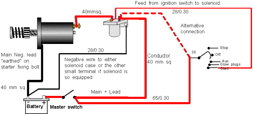
This diagram is straightforward with the cable sizes shown upon it. If the ignition switch is a long way from the engine, increase the cable sizes to and from the switch.
The main battery cables are shown in cross sectional area of the conductors because normal & flexible cables have different sizes and number of strands.
I always try to mount the solenoid close to the engine, but not on it. This is because I believe that engine vibrations will not do the solenoid any good at all – they may do no harm, but why risk it.
If it is more convenient the ignition feed cable be taken from the solenoid main input terminal.
Fault finding
YES - Motor runs
Check the ignition switch and all leads from the battery, via the switch to the solenoid.
YES - Motor does not run.
Very firmly bridge the two big terminals (make sure your screwdriver touches no other metal). Does the motor run?
Yes – Faulty solenoid
No – Fault in main battery wiring – ensure all terminals are tight and secure on cable.
If cables & battery are OK you have a jammed or faulty starter
NO – Inspect the solenoid negative (back to battery negative) cable and terminals. If this is OK the solenoid is probably faulty.
Switch to start position and:- |
Possible fault |
| Solenoid clicks. Warning lamps bright | Break
in one of the main battery leads Faulty solenoid Faulty starter |
| Solenoid "machine guns" – series of rapid clicks | Loose
battery terminal(s) Dirty battery terminal(s) look at Neg. Flat/faulty battery. Bad joint between main cable conductor and a terminal. |
| Solenoid clicks – warning lamps dim until switch is released. | Loose
battery terminal(s) Dirty battery terminal(s) look at Neg. Flat/faulty battery. |
| Solenoid silent – warning lamps dim/go out | Loose/bad
connection between battery & ignition switch. Very flat/faulty battery Faulty ignition switch |
| Solenoid silent – warning lamps OK | Loose/bad connection
between ignition switch & solenoid. Faulty ignition switch. |
This is a rare starter for modern diesel boats so no more will be said about it.
A diagram of some of the internal parts of the pre-engage starter is shown below.
Operation
When the solenoid is energised the iron core is pulled to the right. First it moves the pinion to the left. This meshes it with the engine flywheel teeth., and then it closes the solenoid switch contact plate to supply current to the motor.
When the engine fires – and diesels often start to run on only one cylinder and need the starter to help them turn over – the flywheel would accelerate to motor to a speed at which its internals would fly apart. This is prevented by the free wheel that allows the pinion to turn faster than the motor without damage.
The pivot for the lever has to be adjusted on some pre-engage starters to ensure the pinion does not knock the end of the starter motor when it is operated. This should only be required after new parts have been fitted, so check before changing a faulty solenoid.
The pre-engage circuit
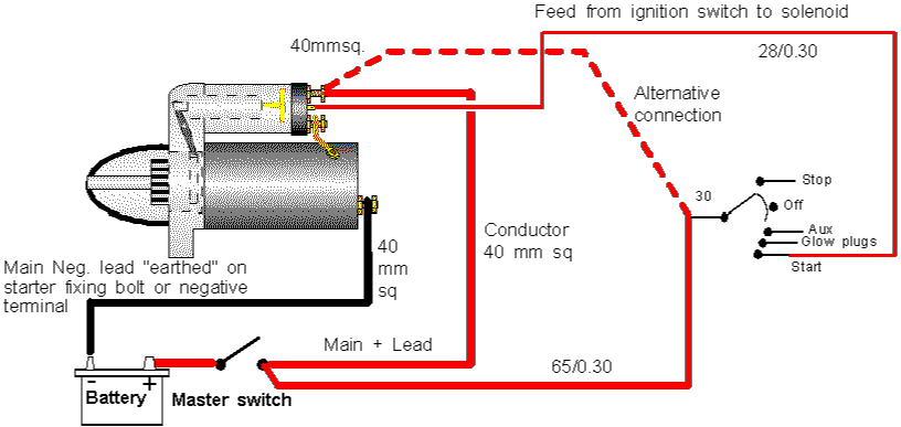
This circuit is very similar to the inertia starter one except the solenoid is mounted as part of the starter.
If the switch and motor are a long way apart – flying bridge or forward control – I would advise the use of a relay. Choose one rated at least at 40 amps, or even use an inertia starter type solenoid.
This circuit is shown below.
Again, try to avoid mounting the relay on the engine to minimise vibrations damage.
The thin negative wire returning to battery negative from the relay may be connected to the same point on the engine as the main battery negative cable.
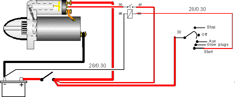
Operation
When the ignition switch is turned to start current is supplied either direct to the starter solenoid, or to the relay coil. If a relay is used, the magnetic field generated in its coil closes the contacts and supplies current to the starter solenoid. Then the process of moving the starter pinion (gear) and closing the solenoid contacts takes place.
Fault finding the circuit
YES – Open circuit (broken wire/loose terminal) between ignition switch and relay.
Open circuit (broken wire/loose terminal) between relay and battery negative.
Faulty relay.
NO – Bridge the two large terminals, does the starter run?
Yes - Faulty relay.
No - Some other starter/circuit fault – continue as below.
No - Open circuit between the battery positive terminal and the starter, or between the starter and the battery negative terminal.
Faulty starter motor (worn brushes).
Yes – Faulty solenoid.
Switch to start position and:- |
Possible fault |
| Solenoid clicks. Warning lamps bright | Break in one of
the main battery leads Faulty solenoid Faulty starter |
| Motor runs but engine stationary | Faulty
freewheel/one way clutch Starter pinion or flywheel teeth stripped (very rare) |
| Solenoid "machine guns" – series of rapid clicks | Loose battery
terminal(s) Dirty battery terminal(s) look at Neg. Flat/faulty battery. Bad joint between main cable conductor and a terminal. Faulty hold-in winding (change solenoid) |
| Solenoid clicks – warning lamps dim until switch is released. | Loose battery
terminal(s) Dirty battery terminal(s) look at Neg. Flat/faulty battery. |
| Solenoid silent – warning lamps dim/go out | Loose/bad
connection between battery & ignition switch. Very flat/faulty battery Faulty ignition switch |
| Solenoid silent – warning lamps OK | Loose/bad
connection between ignition switch & solenoid. Faulty ignition switch. |
Faultfinding with Instruments
The operating of the solenoid is best checked as above, but if these tests are inconclusive use the meter tests below.
NEVER get an ammeter anywhere near a starter circuit. Most of the circuit carries far too much current for an ordinary ammeter to measure.
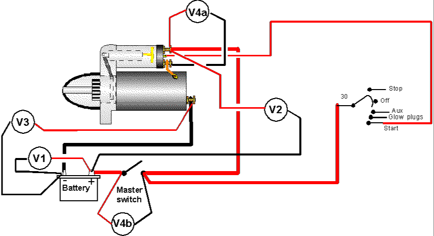
We measure voltdrops and use them to indicate the fault area.
Less than 10 volts = faulty starter (Drawing too much current).
More than about 0.5 volts on V2 or 0.3 volts on V3 indicates excess voltdrop.
Check all connections for tightness, cleanliness and security.
Use tests V4a and V4b to see if the voltdrop is in solenoid contacts or the
master switch. The test can be done across any point you think may be faulty.
Solenoid changing
The solenoid can be changed as an assembly. First inspect the pivot point as detailed on the diagram. If it consists of an "offset screw" and lock nut take care. Fitting a different solenoid may require adjustment of the pivot. If you do not adjust it and it all works, so well and good, but there is a chance you could knock the end off the starter with the pinion.
The solenoid is held onto the pinion or drive end bracket by screws or nuts – these are often very tight.
Undo the fixings and pull the solenoid away from the starter, leaving the iron armature attached. Once you have done that careful inspection should show you how to unclip the armature from the lever.
If the armature is rusty or dirty a good clean up and treatment with something to inhibit rust and possibly a thin film of "copperslip" may well effect a repair.
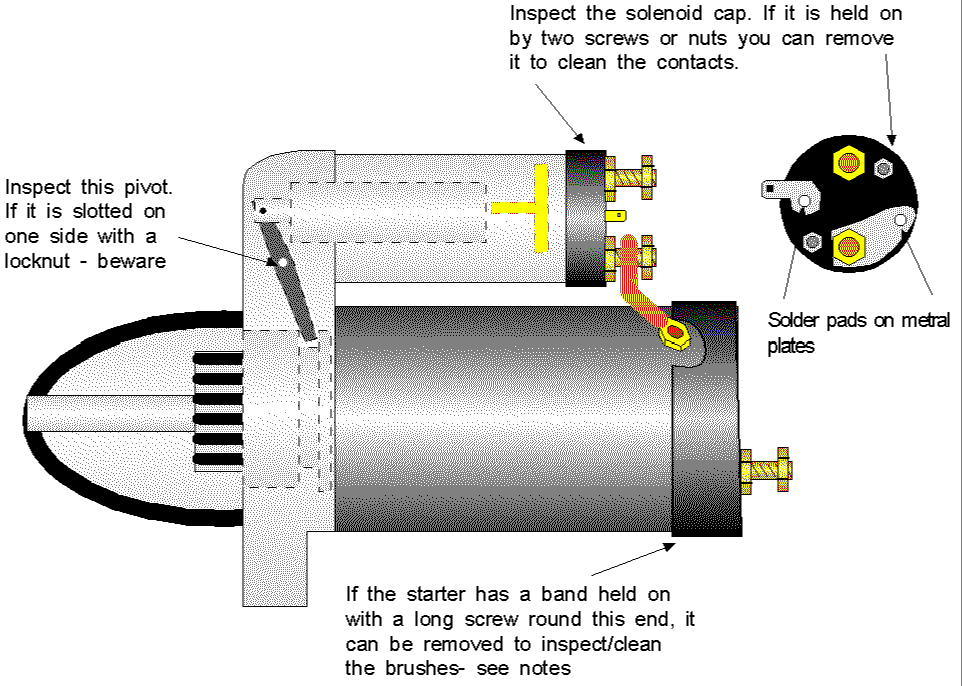
Cleaning Solenoid contacts
Inspect the way the insulated contact cover is held onto the solenoid body. If it is by screws or nuts the cover is removable. If it is swaged or spun on, then you need a whole new solenoid.
Cleaning the inside of the motor & inspecting the brushes
If the end of the motor has a metal band around it, held on with a single screw drawing the two ends together, it can be removed to expose cut-outs that will allow you to clear any copper/carbon brush dust and even wash that end out with something like white spirit.
If you do wash it out either blow it dry with compressed air (difficult) or leave somewhere warm to dry out before replacing the cover.
There should be either a rubber or "cardboard" gasket under this cover to prevent fumes being ignited by sparks from the brushes, so make sure it is correctly replaced.
I would not remove this cover on a petrol boat – even if bilge blowers are in use – use a professional to ensure your insurance is not invalidated!
Summary (starting)
So now you have a boat where you can get light, water etc. in the domestic part of the boat, and you probable think that if you turn the key the engine will start. Well, as long as its summer and a diesel that has a manual stop control, you are probably correct. However if its winter then at least half the engines will not start until we can wire up the glow plugs. If it has some form of electric stop control it will still not start.
First we look at the electric stop controls and then at the glow plugs.