| Back | Home | Index | On |
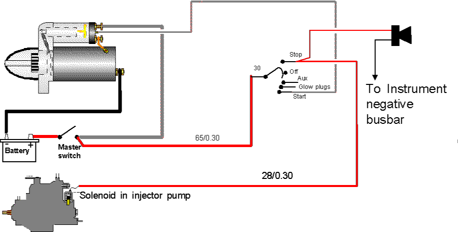
If your engine is a modern, modified, automotive unit it is likely to stop just like a petrol engine, when you turn the ignition off. To accomplish this is an electromagnetic solenoid valve is built into the injector pump. This type of valve needs a supply of current to allow the engine to RUN. This type also needs a supply of current to BLEED the fuel system.
At some engines (Bukh) use a visually similar valve, built into the injector pump, which is only supplied with current to STOP the engine.
Other manufacturers and mariners fit a solenoid to the injector pump’s mechanical stop lever (where the stop cable would normally be fitted). Electrically this type of stop system requires a current supply to STOP the engine. If the engine were within two or three metres of the steering position I would say that the solenoid needs removing and being replaced with a stop cable. That way one ends up with a simple, robust system that does not suffer from wiring and other electrical faults.
So if you have an electric stop control you need to find out if it needs current to STOP or current to run, once you have found that out, you can decide how to wire it up.
Current to RUN
As stated above, this type is most likely to be found on engines derived from cars and vans. We add the circuit to the starter diagram shown below.
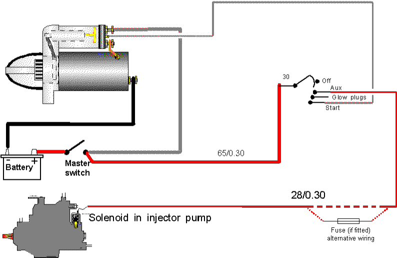
Ideally this circuit will be fused because it carries current all the time the engine is running. However if the fuse blew, the engine will stop at once!
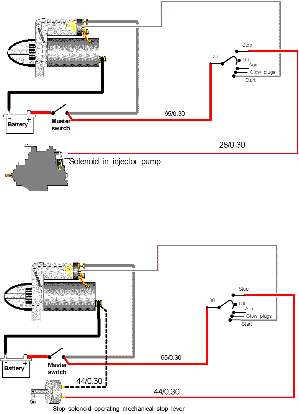
Current to STOP
In this case we need an ignition switch with an anticlockwise from OFF position on it – or a separate push-button. Ideally use a switch that is spring loaded so it returns to off when the engine has stopped and you let go of it.
There have been many stop solenoids of this type burnt out because they have been left turned on all night – let alone the flat engine batteries this produces!
If you can notget/do not have a sprung return switch, fit a "cab buzzer" from a vehicle inside the accommodation. That will ensure you do not forget to turn the switch off.
Connect the buzzer between the ignition switch terminal that is feeding the stop solenoid and any convenient negative point. Later in the book we will look at instrumentation and that will show a negative busbar for the engine electrics.
The thickness of cable for the buzzer is not critical – unless you are into electronics you are unlikely to possess any cable that is too thin.
The solenoids that move the mechanical stop control often draw quite a high current, so you are advised to use a heavy piece of cable, although the solenoids built into the injector pump draw rather less current.
The diagrams for both types of "current to STOP" solenoids are shown below.
The dotted negative cable is shown because some of the separate solenoids have two connections and are "insulated return" so require the dotted negative return cable. Other solenoids only have one terminal so are "earth return" – their return current flows through the engine to the main negative connections, so the dotted line is not needed.
Remember to fit the buzzer, as shown above, if your switch does not "spring back to OFF", alternatively fit a push switch to operate the stop solenoid.
The starting circuit and the "current to stop" circuits are not normally fused because they spend most of the time turned OFF and if a cable did short and start to smoke the natural reaction is to turn the switch OFF.
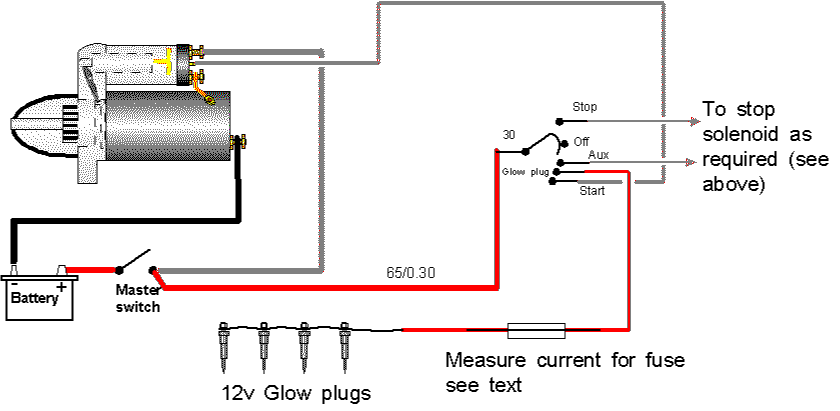
Some diesel engines, especially those derived from light automotive designs cannot get the air in the cylinders hot enough to ignite the fuel under cold conditions. These engines are fitted with an electric heater in each cylinder. We know these heaters as GLOW PLUGS or HEATER PLUGS.
Other engines are supposed to start well enough for most of the time and are fitted with a single electrical heater in the inlet manifold or the back plate of the air cleaner. The Perkins 410/x series of engines have a special hollow "FLAME PLUG" fitted into the manifold. These are connected to a fuel supply, so in very cold conditions electricity heats the electrode in the plug and fuel is drawn through the hollow plug. This produces a "blow lamp" type flame inside the inlet manifold.
Very modern automotive practice is to employ glow plugs, operating on reduced power once the engine starts, to reduce diesel knock and thus minimise annoying the neighbours when cold starting and warming up in the morning. These systems use complicated timer/resister/relay systems but as noise is not normally an issue in marine use I see no reason why the complicated control systems cannot be dispensed with. One would just use a slow count to 30 as a timer and put up with a bit of noise and possibly smoke for a few minutes of running in the interests of reliability and simplicity.
Glow Plug Current Flow
Glow plugs tend to draw a high current. I have measured 75 amps dropping to 45 as they heat up on a BMC 1.8. Our BMC 1.5 draws about 40 amps dropping to 25. One hopes that the ignition switch manufacturer has built sufficient capacity into the switch, but to ensure a long, trouble free life I would advise the use of a very high current relay (180 amp) or inertia type starter solenoid to minimise the current switched by the ignition switch.
There are many boats supplying the heater plugs directly from the ignition switch with no apparent loss of reliability. The diagrams will show a relay/solenoid, but they can be ignored if you wish.
Glow Plug Types
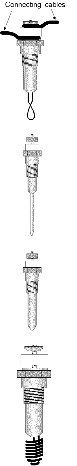 + + |
This plug went out of original
equipment use in the 1970s, but is still found on such engines as BMC 2.2s. This is a 2 volt plug and has to be connected in series with a resistor pack if it is used on a four cylinder engine. The feed MUST be connected to an END of a glow plug bank and runs alternately top of plug insulator to top of next, and the bottom of insulator to bottom of the next. The last plug is connected to the engine block. If one plug fails they all stop working. This is a 12 volt plug and each plug "earths" itself through the engine block. The feed can be connected to any position in the bank and the cable simply runs top of insulator to top of the next insulator. If one plug fails the rest still work. This can cause white smoke for a period after cold starting. On BMC1.5s remove these plugs regularly and clean all the carbon off the "heater pin". If required use a drill 0.5mm larger than the pin to clean carbon from the hole in the head. "Copperslip" pin and thread when re-fitting to assist in the next removal.
This is the modern glow plug. It’s a 12 volt plug and is connected as the "pin type" plug above They tend to draw larger currents than the above types.
This is an "air heater" type plug that may be found in air cleaner back plates. This is likely to be difficult or impossible to source. As far as I know it is a 12 volt plug so is connected between ignition switch and battery negative. |
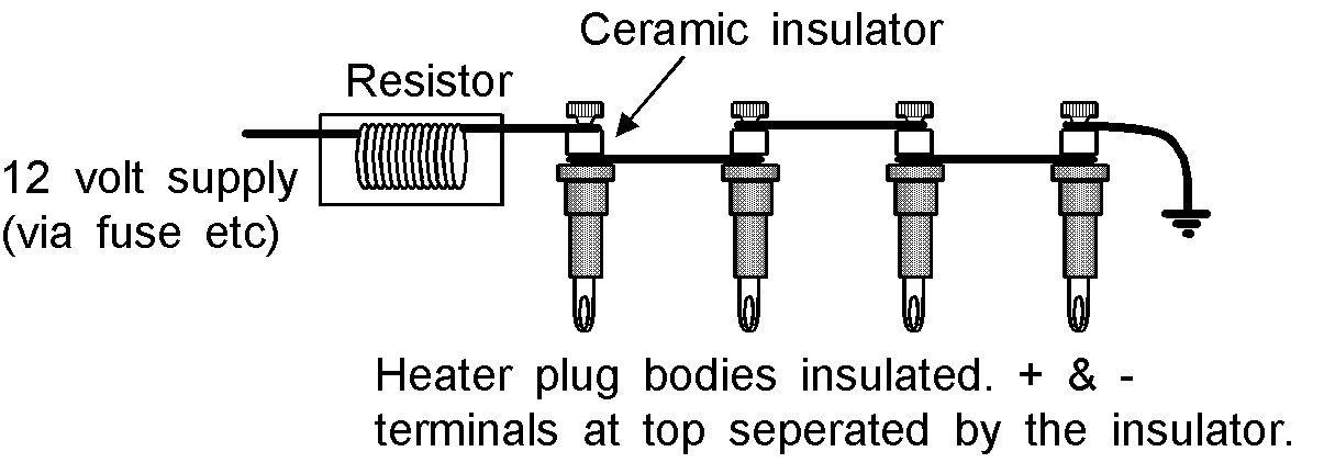
This is the circuit for the old 2volt heater plugs. The inverted triangle symbol on the right shows the negative connection either to the engine block or battery negative.
If the resistor fails and is unobtainable, the problem could be solved by mounting two of the plugs in a ventilated metal box, thereby coupling six plugs in series.
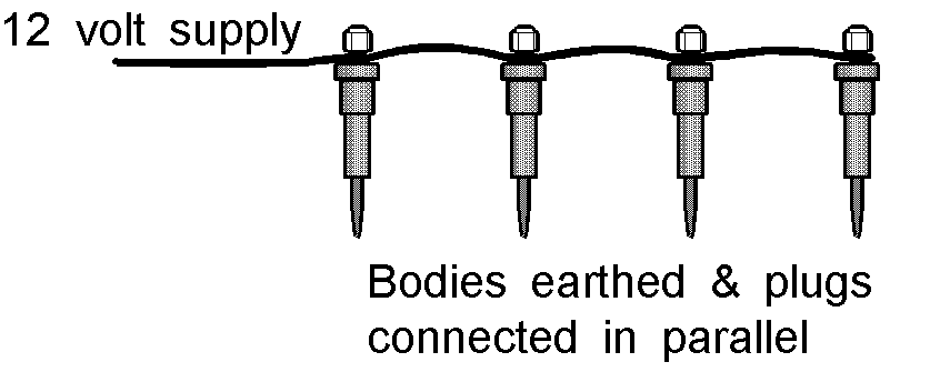
The diagram above shows how the 12 volt plugs are connected together. They "earth" through their metal bodies to the main battery negative connection.
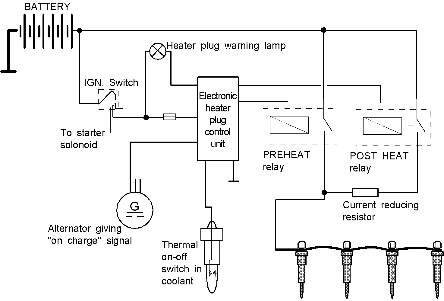
The last diagram is for one of the modern circuits that keep the glow plugs turned on at reduced power once the engine is running. It also uses a warning lamp to tell you when to attempt to start the engine. My advice would be to ignore this type of system and avoid the complexity of the extra sensors, connections, relays and the electronic control unit.
Complete diagrams
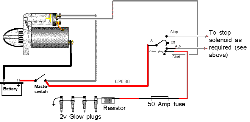
This is the simple version for the 2 volt glow plugs showing the fuse. Locate the fuse in a fuse box close to the instruments and inside the boat’s accommodation where possible. Wire in something like 65/0.30 MINIMUM and thicker if you can.
If the ignition switch is more than two or three metres away from the engine I would advise the use of a relay or solenoid as shown later.
This is the simple 12 volt glow plug circuit.
Locate the fuse in a fuse box, close to the instruments and inside the accommodation if possible.
Because of the different current ratings for these plugs you need to measure the current your particular plugs draw.
Take a thick piece of cable or several lengths of thinner cable, strip the ends and connect to the glow plugs.
If using several lengths twist them together. Fit a 0 to 75 amp dc clammeter to the cable and firmly connect the free end to engine battery positive.
Very quickly take a current reading. It will drop as the plugs warm up. You need both the "plugs cold" reading and the "plugs hot" readings.
Calculate your cable size for the "plugs hot" reading and fuse for the "plugs cold" reading.
If the ignition switch is more than two or three metres from the engine I would advise the use of a relay of solenoid as shown below.
Only the 12volt plugs are illustrated, if you are using the 2volt version simply substitute the plug/resistor diagram for the glow plugs shown.
NOTE – the diagram shows a high current (180-amp) relay. If you are using an inertia starter solenoid wire the ignition switch to the small terminal, connect the case to battery negative in some way (see solenoid section above) and connect the two large terminals between battery positive and the glow plugs.
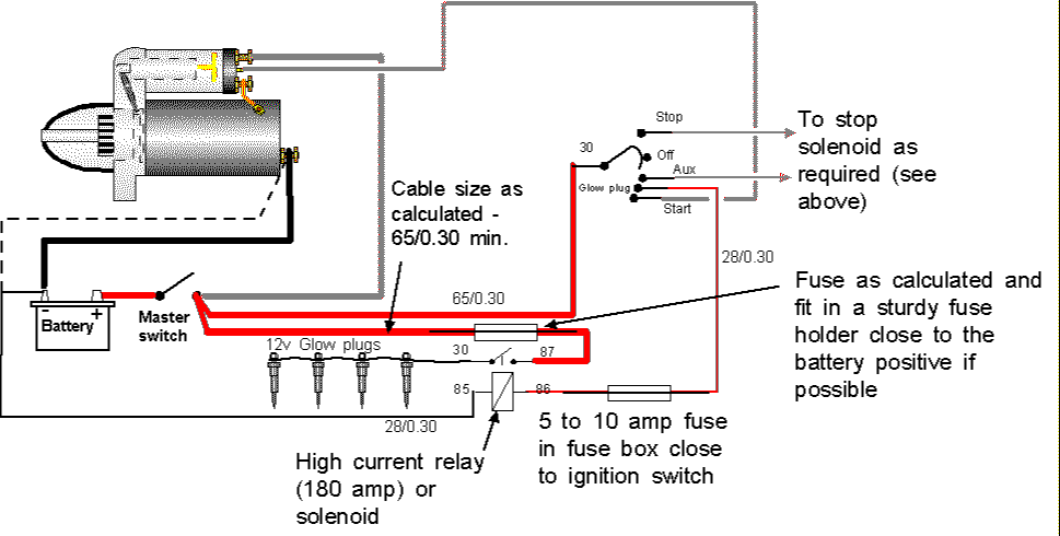
Note the dashed alternative of wiring the negative back to the main negative terminal on the engine block if other components require this form of connection.
There is virtually no maintenance to do apart from checking:-
Check all connections for security and cleanliness
Check the current flow
Remove the 12 volt plugs and clean carbon off the tip at (say) every third year.
Glow plug fault finding
Testing glow plugs
12 volt plugs
Remove and using jump leads connect to the engine battery – take care where you hold it and DO NOT allow the jump lead clips to touch each other.
Each plug should glow red-hot after a moment or two.
2 volt plugs
Inspect the tips – you will easily see any that have melted.
Connect an ohmmeter across each plug. If the metre shows the upper case "i", the plug is faulty.
If all the above fail to locate a faulty plug, rub oily hands over the tip and extremely quickly "flash" jump lead from battery connections across the plug – if the tip smokes its working. If you are too slow at "flashing" and the tip melts the plug was ok, but now it is faulty. If the jump lead does not spark and the tip does not smoke the plug is faulty.
Only undertake the last test if all others fail and BE QUICK.